• The move to the new server is done. There are some software and database maintenance updates in process. This has us passing the hat around to help out. We appreciate any donations. Seriously, even a dollar helps. The payment page may be found here - https://www.audiokarma.org/support.html

Need help on rebuilding amplifer for luxman l-85v

david252

New Member
Hi,

I have bought the luxman l-85v that amplifier stage needs to be re-built.
I have gone through the service manual to order similar parts and I have solder them just few days ago. I thought that the as long as the amplifier stage is rebuilt it will work flawlessly. But two resistor on the left amplifier has been burnt when increasing the volume. But anyway, tried to listen to music with the right amplifier with earphone connected to phone connection but I hear nothing. Am I able to hear the music without the amplifing stage or is in order to output the audio to phone connection do I need to set the speaker to A or off?
Also the amplifier does not get warm which is strange.
Do you guys have any idea where to look for the problems??

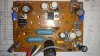
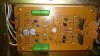
When I see the pre-amplifier board there are some diode missing is this normal?
Do you see any wrong placement in the amplifier board?
I have replaced all the capacitor except for the preamplifier part.

Any one who has the experience fixing the luxman l-85v would be appreciated.
 

Attachments

  • DSC_0072.jpg
    DSC_0072.jpg
    68.5 KB · Views: 97
  • DSC_0074.jpg
    DSC_0074.jpg
    59 KB · Views: 90
  • DSC_0076.jpg
    DSC_0076.jpg
    67.5 KB · Views: 90
Register to hide this ad
The headphone is before the speaker switch, so you should have sound no matter the setting of the speaker switch.
Did you verify the value of the parts on the boards with the listing in the service manual? Service manuals can often be incorrect.
I would make a dim bulb tester before proceeding further.
 
first things first....I'm a nube and what I can tell you is what I've learned at AK.
I always value the input from others with more experience than myself.
That's how I've learned.

First try to identify where the general/main issue(s) are located. When you say "phone jack"...you mean head set jack? And you don't hear music from your headset,,,yes?

If so, It appears you may have issues in both your preamp and amp sections with no sound from headset and burnt resistors on amp board, respectively. Going blindly on this without a schematic...I'll talk in general terms.
I'll try to get hold of a schematic from hifi-engine

Try to your preamp working first.
What I would check for in preamp:
1. check validity of missing diodes and what role they play in circuitry)
2. deoxit switches, pots etc...check solder joints
3. headset jack wiring, volume pot wiring etc...and continuity
4. check schematic for dual power supplies (one for preamp and one for amp)
check preamp power supply cap voltages if good then check rail voltages
 
Thank you for your replies.

I am going to make the dim bulb tester this week.
Dim bulb tester indicates whether there is short circuit in the amplifier, am I correct??

I will be ordering caps for the pre-amp stage and try to replace them and test them.
Also for the missing diode, I guess in the service manual it does not have any values for four of the diodes so I guess it was omitted for a reason. I did take a picture of one of the main amplifier stage but it was missing already quite of the components so it really does not help me. I have replaced all the values that was indicated in the service manual. If there was discrepancy what should I do?

When powered on the pre-amp stage transistor do get warm which tell me that it is working. But whether it outputs correct signals, I think I would perform dim bulb test and go from there.

It is strange that the main amplifier stage transistor do not get warm, there is power going in to the amplifier but nothing is happening at the moment

When I get the dim bulb test I will post it again to get some advice probably tomorrow.

Thanks
 
First try to identify where the general/main issue(s) are located. When you say "phone jack"...you mean head set jack? And you don't hear music from your headset,,,yes?

s

main amp is PB1037 and pre-amp is the PB1033

phone jack I was referring to is the headphone jack in the front panel.

Thank you for your advice I will post again when I perform the dim bulb test

Thanks
 
I believe their is a short circuit,,,,you may have blown one two etc... output transistors and possible some driver trans as well from the burnt resistors you mentioned especially if these resistor were base resistors. Have you checked the fuses,
is your unit in protection mode? Try removing the loop horseshoe shaped bar in the back(if there is one) or switch that goes from "pre-out" to "main-in". Then try headsets. you will have then disconnected the preamp from the amp,

I wouldn't perform a dim bulb test at this stage. Identify the location of the blown transistors on your schematic.....if its a driver transistors, desolder it, test it. then check the transistor in the path (if it's an output trasnsistor...most likely shorted as well.
 
Last edited:
Hello guys,

I have just done the dim bulb test. When I turn on the amp bulb lights up brightly but dims right away, so I think it passes the dim bulb test.

I did for got to mention that when I first connected rebuild left and right amplifier it did blow the main fuse(125V 5A) but that was because I have put the T0-3 type transistor in opposite way(switched 2sc1070(Q11) and 2SA679(Q12)). Once I have replace the fuse with (250V 3A) and replace the caps in correct place it was fine. Then I was trying to hear the music through the headphone and slowly increased the volume the left amplifier R20 and R21 has been burnt. Those resistor are 82ohm with 1/2W.


Also What do you mean by protection mode?? where should I look it it is in that mode ??? and what should I do to bring it back to normal mode.
Also there is no horseshoe shaped bar at the back.

Right side of amp have no issues but even though I turn my amp on it does not get warm. I will try to test the transistors to see if there is any blown TR, but I doubt it cause all of TR is TO-18 cased and has high temperature as well as the high Power dissipation compare to original components.

I guess now I will try to desolder all the transistor and test them if there exists any burnt transistors

If there is any other test I should do please let me know

Thank you for your help
 
Your confusing me as to what your issue is...you say "right side of amp has no issues" and you can't hear anything from your headset (again two different issues (preamp + amp).

Just answer these few questions as a yes or a no.

1. Do you have another stereo unit that you could feed the L-85 into?
2. When you turn the L-85 on, can you hear the relays click?
3. Can you hear music from your right channel at the speaker?
3. Can you hear music from your headset? if so which channel
4. When you originally placed the components in incorrectly did you reuse them?
5. If you reused them did you test them?
6. When you blew the fuse...did you test any of the surrounding components that possibly could be damaged?

In the mean time I'm going to look at the schematic

1. yes I am using RCA cable with smartphone to feed feed the audio for test purpose.
2. yes
3. no
4. no
5. yes. Yesterday and today I have tested the transistor to see if it is still working by desoldering it and testing them I have found quite of few transistor that is dead. Need to re-order those I do not have any extra component at the moment.
6.surround component is meant by power and preamp stage? I will order capacitor for preamp to replace old ones and for power it is outputting correct voltage to amplifier.

Thanks
 
good...except your reply on questions #1 and #6. I worded #1 incorrectly.
I have three more new questions #7,#8 and 9.

1. do you own any other system(s) that is considered an amplifier and a preamp
ie: your system is a preamp and amp unit all in one. If not can you borrow one

6. When the fuse blew, certain components got toasted right. As of yesterday you found more bad components. are they all near each other on the schematic and which channel L or R

7. Are all of your issues with bad components in left or right channel or both. You since found other components to be dead that are not replaced left or right channel.

8. List components and schematic #'s by left or right channel include the fuse# that you replaced include circuit board # as well.

9. list the components and schematic #'s that you believe are bad that have not been replaced by channel L or R

I got hold of the schematic, could you post a pic of the back panel?

If I were you, I would Stop replacing components at this time. There are other issues going on. Take a moment to assess. In general when components get toasted mostly from shorts it takes out other components in its path. You need to trace those surrounding components on the schematic, If you believe one channel is operable take voltage measurement comparison to see differences between L and R.
I believe you have other issues that are being picked by PB 1038. Bad caps will cause too much ripple and can be in power protection mode.
 
Last edited:
good...except your reply on questions #1 and #6. I worded #1 incorrectly.
I have three more new questions #7,#8 and 9.

1. do you own any other system(s) that is considered an amplifier and a preamp
ie: your system is a preamp and amp unit all in one. If not can you borrow one

6. When the fuse blew, certain components got toasted right. As of yesterday you found more bad components. are they all near each other on the schematic and which channel L or R

7. Are all of your issues with bad components in left or right channel or both. You since found other components to be dead that are not replaced left or right channel.

8. List components and schematic #'s by left or right channel include the fuse# that you replaced include circuit board # as well.

9. list the components and schematic #'s that you believe are bad that have not been replaced by channel L or R

I got hold of the schematic, could you post a pic of the back panel?

If I were you, I would Stop replacing components at this time. There are other issues going on. Take a moment to assess. In general when components get toasted mostly from shorts it takes out other components in its path. You need to trace those surrounding components on the schematic, If you believe one channel is operable take voltage measurement comparison to see differences between L and R.
I believe you have other issues that are being picked by PB 1038. Bad caps will cause too much ripple and can be in power protection mode.

1. no I do not own any amps and I dont think I could borrow one at this moment.

6.Both L and R had same component blown. Transistor for PB-1037 are Q6,Q7,Q8,Q10

7. problem is on the left and right. I have gone through all the transistor to find which ones are dead for both left and right

8. PB-1037 - Q6,Q7,Q8,Q10. Fuse is the 125V 5A (replaced with 250V 3A) it is right beside the PB-1039 but cannot find on schematic I will upload the picture of it.

9. Like I said above, I have tested all the transistor and capacitor does not show any damage and I doubt the resistor will have problems.

Thanks for your help
 

Attachments

  • DSC_0077.jpg
    DSC_0077.jpg
    71 KB · Views: 50
  • DSC_0078.jpg
    DSC_0078.jpg
    52.5 KB · Views: 46
okay now that I have time and I am spending tons of time trying to make the amp work.
Last night finally got my two amplifiers working without any issues(amplifier heat sink is warm hot but not hot hot), but still no sound.

I tried to feel the temperature of preamp(pb-1033) transistors but it is cold, so is it safe to say that the transistors are dead? Ive used mutimeter on dc and try to see the voltage drop through resistor before and after the transistor. Before it reads about 350mA but after it reads 0.03mA(which means nothing)

Can I test the transistors with the multimeter on the diode setting, without desoldering them??

Also need help on how to bias the voltage of the amplifier, I am looking at the service manual but do not understand where I should put my two leads of multimeter. Also to bias it, I need to change the verector but it is hard to reach. Is it okay to keep the amp powered on and change the turns of verector? I am worried that I might touch some components while reaching for the verector.

Any help will be appreciated

thanks
 
Hi, guys

I am working hard to get this amp working and running again, but still no sound after replacing many component.

Currently I am inputting test tone of 1KHz from phono 1 and I get output from the equalizer amplifier(PB-1003) of 10V from both left and right. However, I do not get any output from the speaker nor headphone.

Can anybody give some leads where I should look for to find out the problems?
I am looking at the schematics of the whole amplifier but do not see where the output of the main amplifier heads to.
I am thinking that it is pin number 818,811,828,829,824, and 821. I get about 1.5V to 2V from those pins is this normal?

Any help will be appreciated

Thanks
 
Please, don't use the phono input for debugging your amp. You may damage the phono preamp (10V at the output of the phono preamp is too much). Use the Aux1 or any other high level input.

With test tone on the Aux input, see if you have signal at the input of the main amplifier board. The pin 813 on the protection circuit board (the one with the relay) is connected to the input of the left channel power amplifier, and pin 816 is connected to the input of the right channel amplifier.

If you have signal at the input of the amplifier board, see if you have a signal at the output of the amplifier. On board PB-1037 there is a trace common to R20, R21, R23 and R24. That trace is the true output of the amplifier and you should look for signal here. This point is before the protection relay and usually reveals things that you may not see at the speaker output if the relay is not closed, or if the relay has bad contacts. By the way, R23 and R24 are possibly open from your inversion of the power transistors. Measure the resistance of R23 and R24.

828 and 829 = main negative power supply rail. Something like -40 to -50V would be normal here.

821 and 824 = main positive power supply rail. Something like +40 to +50V would be normal here.
 
when your saying about R23 and R24 are you referring to R22 and R23?? ther is no R24 in PB 1037.
also with mutilmeter will AC setting is correct way to observe the signal?? should both lead be measuring the voltage drop between the resistor??
what will be the okay voltage at this point??

thank you for the help
 
Hope fully useful comment. I wonder about the collector connections. TO-3 and TO-220 the tabs and cases are also connected to the collectors. Did you omit any spacers (usually plastic or nylon inserts) when replacing the driver transistors? (If they are used - depends on what they are screwed into). Also the smaller metal can transistors the case is also the outside - looks like in one they may be touching each other and that may cause problems. My 2 cents.
 
As putting input as aux 1 and measuring pin 107 and 108 in DC setting in the multimeter I get 2.2mV for both.
And the output of the equalizer amplifier which is pin 105(5.4mV) and pin 106(10mV)

For pin 813 and pin 816 shows 3.3mV as DC(doesnt seem right to me)

For pin 828 and 829 I get -30V and for 824 and 821 I get +30V

Also for measuring the main amplifier is it okay to take them out of the heatsink and measure them? I am worried it might get to hot.


Thanks
 
Last edited:
Hope fully useful comment. I wonder about the collector connections. TO-3 and TO-220 the tabs and cases are also connected to the collectors. Did you omit any spacers (usually plastic or nylon inserts) when replacing the driver transistors? (If they are used - depends on what they are screwed into). Also the smaller metal can transistors the case is also the outside - looks like in one they may be touching each other and that may cause problems. My 2 cents.

I did not omit the plastic inserts.
Also for the metal can transistors the outside matters?? even though they have collector legs?? currently none of the cans are touching each other just to make sure

Thanks for the comments
 
I think I finally found the problem.
I got sound when I have connected only right channel main amplifier.

The relay does not make click sound when two channel are all connected.
So I tried with only left channel connected and still no click sound.
So I think I should recheck the transistors on the left channel.

Can this also be the bias problem of left channel??

If so, how can I bias this l-85v(dc offset and idel adjust)

I am looking at the service manual but would like to get help before I tackle it.
Such as where to put two leads of the multimeter and so on.

Thanks for your help guys.
It is great feeling when l-85v finally gave me a sound
 
Last edited:
Back
Top Bottom