• The move to the new server is done. There are some software and database maintenance updates in process. This has us passing the hat around to help out. We appreciate any donations. Seriously, even a dollar helps. The payment page may be found here - https://www.audiokarma.org/support.html

Need help repairing Yamaha A-560 amplifier

PauliusA

New Member
Recently I picked up a "fully working" Yamaha A-560 amp for cheap and it has one small problem - it isn't fully working (gasp)... Sound coming from the left channel is distorted. What I've found out is that both output transistors of that channel were not even connected to PCB. After checking them it appears that both are dead. Does the fact that I have sound (albeit distorted) in left channel indicate that I can just put in new transistors and everything will work? Or should I check something else before putting in new transistors? I don't want to put in new ones only to see them going dead. I am able to tell capacitor from transistor, to read simple diagrams and to use digital multimeter, but I'm far from electronics expert.

Other interesting thing is that instead of 2SA1106 and 2SC2581 this amp has 2SA1186 and 2SC3263 in both channels. And as far as I can tell the right channel works perfectly fine with these transistors. So I decided to go with the same transistors for the left channel. Is this decision smart?
 
Register to hide this ad
Welcome aboard..
Is this decision smart?
No... These outputs really should be complementary pairs...

2SA1106 complements 2SC2581

2SA1186 complements 2SC2837

2SA1294 complements 2SC3263
 
Yamaha amplifiers are notorious for collateral damage when outputs short out.
 
Post some clear close up photos of the left channel component side and solder side of the circuit board.
 
Thank you very much for your help. My camera is not the best but I've tried my best. I'm ready to take more photos if needed. And I'm curious about transistors. Why would you choose pair of 2SA1294 and 2SC3263 and not, for example, a pair of 2SA1186 and 2SC2837?

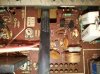
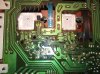
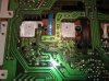
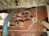
IMG_20210317_200159.jpg IMG_20210317_200524.jpg IMG_20210317_200511.jpg IMG_20210317_200330.jpg
 
Last edited:
This piece has been worked on before
But all components, apart from transistors, should be good (at least from visual inspection)?
Oh by the way, someone on reddit said that I should calibrate some kind of voltage before putting new transistors so it should be ~0 volts. By looking at the amp I see that there is one potentiometer that I can turn using a small screwdriver (named "IDL", near "MAIN LCH" text). Is this the potentiometer used to change that voltage? And where should I measure the voltage?
 
Is this the potentiometer used to change that voltage?
IDL is idle current or bias and needs to be adjusted after replacing any transistors in the amplifier circuit. The procedure for adjusting idle current is in the service manual.
 
Back
Top Bottom