• The move to the new server is done. There are some software and database maintenance updates in process. This has us passing the hat around to help out. We appreciate any donations. Seriously, even a dollar helps. The payment page may be found here - https://www.audiokarma.org/support.html

Need help to decipher indicator lamp specifications

Corktowner

Active Member
Hello again. I am still working on the JVC A-X9 and as the title indicates I have moved onto the lamps. After some searching through the forums I didn’t find any hints. The service manual also doesn’t offer any specs not the lamps (but it does show three different part numbers). However the manual does offer some hints, which I am hoping someone here has enough knowledge to decipher.

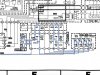
The first lamp circuit has 5 bulbs in series, and with the power and SPK-1 activated, shows 14.6V feeding the two lamps. If they are the same, then 7.3V drop across each. No word on the current. Point 20 is ground.

4468E23A-9886-4135-B708-24352A51EF52.jpeg

The second lamp circuit has 7 maps in series with some RC circuits connected to the switches. I traced the circuit and I found that the REC and MM switches are activated. The same 14.6V feeds these two lamps, but I don’t know what effect the RC circuits have.
FAF1CE29-0B29-45E8-AB01-2111BF1F106C.jpeg

Lastly, I built a simplified model of these in iCircuit and played around with the lamp values. I don’t know enough yet to use those results, but the most interesting thing about the two circuits is that they always had the same current no matter what switch configuration I used. So perhaps the two PNP BJTs hooked up at their bases act as a current limiter? Again, I don’t know enough to use those results.

If anyone knows these lamps, or knows enough about circuits to determine the specs, I’d appreciate the help. My goal is to change these over to LEDs.

Thanks!
 
Register to hide this ad
8 volt lamps seem awful common, with 30 - 40 mA of current draw. A picture of one of the lamps might be helpful.
 
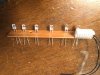
Here are the lamps and one of the series boards.
DDC0CFFE-CB17-49B8-B62F-8EB871E59917.jpeg 55687714-3084-4593-AC42-D838A99CA1F5.jpeg

The service manual lists three part numbers for indicators:
EWS018-008 on the muting, tape and input circuit
EWS016-006 on the speaker and tone circuit
EWS012-001 (called lamp, not indicator) on the speaker and tone circuit.

All of the lamps appear to be the same physically. Each lamp on the speaker and tone circuit was burned out, so I couldn’t measure any of their resistance.
 
Did the lamps have color condoms on them? That might be the difference in part numbers. Look at other amp's service manuals in this line up for clues on ratings. For example I have an R-X40 receiver. It's similar to the R-X60 and R-X80, each being higher powered with more features like a lighted EQ. The parts list / schematic for the R-X80 doesn't describe the bulbs but the information is in the schematic for the R-X60. You used to be able to search part numbers on JVC's website. They have taken it down. It would tell you what units used that part. That could give a clue if you looked at those scematics.
 
Where are you seeing series connection? Pretty sure there is NO way for that to work for indicator lamps that have to be able to light independently of each other. And, the schematic sure looks like the switches share a common hot side with ground (or the lower voltage side controlled by individual switches.

That being the case, these are probably something common like a #2182 14V/80mA lamp.

John
 
Did the lamps have color condoms on them? That might be the difference in part numbers. Look at other amp's service manuals in this line up for clues on ratings. For example I have an R-X40 receiver. It's similar to the R-X60 and R-X80, each being higher powered with more features like a lighted EQ. The parts list / schematic for the R-X80 doesn't describe the bulbs but the information is in the schematic for the R-X60. You used to be able to search part numbers on JVC's website. They have taken it down. It would tell you what units used that part. That could give a clue if you looked at those scematics.

There are no color covers or other features on the lamps. They all look identical, as well. I checked a few of the other JVC A-X series, but they all do something different for the lamps, and none of the service manuals have any more detail.


Where are you seeing series connection? Pretty sure there is NO way for that to work for indicator lamps that have to be able to light independently of each other. And, the schematic sure looks like the switches share a common hot side with ground (or the lower voltage side controlled by individual switches.

That being the case, these are probably something common like a #2182 14V/80mA lamp.

John

The lamps are definitely in series. There is just a system of “off ramps” for the current in case the lamps are not supposed to be lit. That is effectively what the switches do.
 

Attachments

  • F98642BF-E2A2-44D8-AD26-C3CC84C56931.png
    F98642BF-E2A2-44D8-AD26-C3CC84C56931.png
    456.2 KB · Views: 12
I ended up ordering 14V LEDs from dgwojo based on my reading of the circuit and his recommendation. He said on his bench the LEDs run fine from 5-14V, and they won’t require a resistor. I’ll just have to make sure the polarity is correct when I install them.
 
Looks like the bulbs are lit "2 x 2". 8 volts bulbs would be consistant with two of them across a 15 volt supply.
 
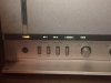
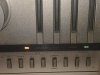
Good news - it seems that the 14V 4mm white LEDs did the trick. Here are the results:637F98CE-1E28-4B59-8E8C-2B85409D205E.jpeg

One of the series boards with the LEDs installed before trimming.

6B0A4191-578A-475E-BA14-3F0BE3F58A35.jpeg F3F976F3-DB7F-43DF-B211-0D1BAC53F9D1.jpeg

The color is pretty even on each function (despite the camera flash washing it out), except for the subsonic. I guess there is just too much text in that word for one bulb. Special thanks to @dgwojo for working with me on the lamps and then sending them out quick.
 
I wanted to revisit this thread because there ended up being a lot more to the story...I am not 100% sure it is finished, but I think I'm there.

So, when you last left me I was thanking the special guests and the audience for a wonderful evening. Unfortunately it didn't last very long - one of the newly installed LED burned out after a few hours. I didn't know much about LEDs at the time, but I did know they should last a bit longer than one listening session.

I also found that two new capacitors in the lamp circuit were bulging to the point where I was concerned they would pop their tops...in other words, all was not well.

After much internet circuit education, I determined that the power supply for the lamps on the A-X9 is a special constant current circuit using a PNP transistor...actually it is two such circuits. One for the Power, speaker and tone controls, and one for the muting, input and tape monitor. In retrospect it makes sense - how else can a set of lamps in series be managed except through constant current? Constant voltage would have the lamps getting dimmer each time one more was switched on.

With my new found (but terribly limited) knowledge, I tried to find the solution. I put a resistor into the LED circuit, but that just caused the PNP transistor controlling it to really jack up the voltage to keep the current correct. So I burned out a few more LEDs with that attempt.

I checked out some more internet resources, and after much study of the service manual I decided that the value of the two resistors leading into the power circuits could be raised and this would drop the constant current to a level suitable for the LEDs. As luck would have it, this has worked. The previous current in the lamp circuit was about 34mA, and now it is about 5mA. The change was from 150 ohm to 470 ohm resistors. 470 just happened to be what I had on hand in 1/2W, and they did the trick.

So, if anyone else with one of these rare beasts would like to go to LEDs, change out R481 and R482 for a higher value and you’ll be all set. Of course if a few hundred hours of use prove that statement wrong, I will let you all know.BE4C72B5-3763-46C5-A740-D9689D2BFCB7.jpeg
 
Last edited:
Good detective work. Yes, it looks like X437 and X438 are configured as current sources. And your 'adjustments' were appropriate. Just another example of why it is not always possible to simply replace an incandescent with and LED (with or without an added series resistor).
 
I wanted to revisit this thread because there ended up being a lot more to the story...I am not 100% sure it is finished, but I think I'm there.

So, when you last left me I was thanking the special guests and the audience for a wonderful evening. Unfortunately it didn't last very long - one of the newly installed LED burned out after a few hours. I didn't know much about LEDs at the time, but I did know they should last a bit longer than one listening session.

I also found that two new capacitors in the lamp circuit were bulging to the point where I was concerned they would pop their tops...in other words, all was not well.

After much internet circuit education, I determined that the power supply for the lamps on the A-X9 is a special constant current circuit using a PNP transistor...actually it is two such circuits. One for the Power, speaker and tone controls, and one for the muting, input and tape monitor. In retrospect it makes sense - how else can a set of lamps in series be managed except through constant current? Constant voltage would have the lamps getting dimmer each time one more was switched on.

With my new found (but terribly limited) knowledge, I tried to find the solution. I put a resistor into the LED circuit, but that just caused the PNP transistor controlling it to really jack up the voltage to keep the current correct. So I burned out a few more LEDs with that attempt.

I checked out some more internet resources, and after much study of the service manual I decided that the value of the two resistors leading into the power circuits could be raised and this would drop the constant current to a level suitable for the LEDs. As luck would have it, this has worked. The previous current in the lamp circuit was about 34mA, and now it is about 5mA. The change was from 150 ohm to 470 ohm resistors. 470 just happened to be what I had on hand in 1/2W, and they did the trick.

So, if anyone else with one of these rare beasts would like to go to LEDs, change out R481 and R482 for a higher value and you’ll be all set. Of course if a few hundred hours of use prove that statement wrong, I will let you all know.View attachment 2103162
 
I wanted to revisit this thread because there ended up being a lot more to the story...I am not 100% sure it is finished, but I think I'm there.

So, when you last left me I was thanking the special guests and the audience for a wonderful evening. Unfortunately it didn't last very long - one of the newly installed LED burned out after a few hours. I didn't know much about LEDs at the time, but I did know they should last a bit longer than one listening session.

I also found that two new capacitors in the lamp circuit were bulging to the point where I was concerned they would pop their tops...in other words, all was not well.

After much internet circuit education, I determined that the power supply for the lamps on the A-X9 is a special constant current circuit using a PNP transistor...actually it is two such circuits. One for the Power, speaker and tone controls, and one for the muting, input and tape monitor. In retrospect it makes sense - how else can a set of lamps in series be managed except through constant current? Constant voltage would have the lamps getting dimmer each time one more was switched on.

With my new found (but terribly limited) knowledge, I tried to find the solution. I put a resistor into the LED circuit, but that just caused the PNP transistor controlling it to really jack up the voltage to keep the current correct. So I burned out a few more LEDs with that attempt.

I checked out some more internet resources, and after much study of the service manual I decided that the value of the two resistors leading into the power circuits could be raised and this would drop the constant current to a level suitable for the LEDs. As luck would have it, this has worked. The previous current in the lamp circuit was about 34mA, and now it is about 5mA. The change was from 150 ohm to 470 ohm resistors. 470 just happened to be what I had on hand in 1/2W, and they did the trick.

So, if anyone else with one of these rare beasts would like to go to LEDs, change out R481 and R482 for a higher value and you’ll be all set. Of course if a few hundred hours of use prove that statement wrong, I will let you all know.View attachment 2103162
Wow, I work on my A-X9 in same time like you , last year, burned unlimited sets of LEDs with 510ohms resistors on them , also new 10uf caps just installed
wend bad in a week!
I would go for the R481 and R482 but my question is ; do you have 14V LED in it at this time, or you have just regular LEDs?
 
I would go for the R481 and R482 but my question is ; do you have 14V LED in it at this time, or you have just regular LEDs?
LEDs are current driven devices, not voltage driven. A "14 volt" LED would simply be an LED with a built in current limiting resistor. That resistor would be sized such that the LED/resistor drew nominal current with a 14 volt source.
 
LEDs are current driven devices, not voltage driven. A "14 volt" LED would simply be an LED with a built in current limiting resistor. That resistor would be sized such that the LED/resistor drew nominal current with a 14 volt source.
I guess my questions should had been
If I change the resistors by the current sources , I still need a limiting resistor on each LED?
 
Theoretically, you do not need a resistor. In practice, I think I would add series resistance so that the collector voltages of X437 and X438 were as specified on the schematic (about 14.6 volts). With 5 mA, perhaps start at 1.8K.
 
Back
Top Bottom