• The move to the new server is done. There are some software and database maintenance updates in process. This has us passing the hat around to help out. We appreciate any donations. Seriously, even a dollar helps. The payment page may be found here - https://www.audiokarma.org/support.html

Need Help With 440A

Kasanay

Active Member
I just acquired a Fisher 440A (no pre-amp). I plan to use this as a stand-alone and is my first tube project.
I have powered it up, plugged in a ipod & speakers and it works (kind of). There is a fair amount of hum and I can only play it at very low volume levels - anything higher and there is massive distortion on the speakers.
I will be removing some of the unneeded wiring and will order replacement caps. but I have a few mysteries that need solving:
The voltage issue - I understand that because the pre-amp is no longer connect, I need to compensate with some resistors. I was able to gain a lot of info from this thread. The referenced amp on that thread is a 660A. I need to know if the same values apply to my 440A.
Removing Resistors - Can I remove R124 & R127 & disconnect C93B & C93 (the 60uF caps) as mentioned in this thread?
Thanks,
-Joe


Register to hide this ad
Joe; The 660A and 440A are different variation of the same family (ie: cousins) HOWEVER. The 660A uses 7591 output tubes and the 440A uses 7189's. Different tubes and different circuits, so the 660A values won't work for the 440A. Start with the values in the 460A thread as it's the successor to the 440A. The 4xxA series of amps are all basically the same amp(siblings), with the exception of the 481A(1964) which uses 12ax7's vs. 7247's (12dw7) for drivers. The 7247, is Twin Triode, which is a 12ax7 on one side and a 12au7 on the other. So swapping the 12ax7 and 12dw7 them is not a good idea. There are some variations from year to year, but the basic amp is the same for familial purposes.

Start with the 460A thread as a baseline, and change resistances as needed. Some of the tuners that aren't there anymore had 3 tubes fed off the amp, while others had 4. You need to determine which tuner went with the 440A. www.fisherconsoles.com will have the info. Look in the CUSTOM ELECTRA section from 1962 to 1964 and pull the manual that uses the 440A.
 
The Custom Electras used three 12AX7 tubes on the preamp chassis, with their 12.6 volt heater connections connected in series to form the output stage cathode bias network. Fisher would then typically specify about 33 volts be dropped across these heaters (11 vdc per tube), as set by a single bias control on the power amplifier chassis.

In lieu of the heaters, an appropriate resistor to use in their place would be a 270 Ohm 10 Watt unit. The bias control would then be adjusted for 33 vdc across this resistor.

I hope this helps!

Dave
 
Last edited:
The Custom Electra's used three 12AX7 tubes on the preamp chassis, with their 12.6 volt heater connections connected in series to form the output stage cathode bias network. Fisher would then typically specify about 33 volts be dropped across these heaters (11 vdc per tube), as set by a single bias control on the power amplifier chassis.

In lieu of the heaters, an appropriate resistor to use in their place would be a 270 Ohm 10 Watt unit. The bias control would then be adjusted for 33 vdc across this resistor.

I hope this helps!

Dave
Are you Kidding??? This is an incredibly huge help! It would have taken me days of research to get even close the correct values - not to mention all the mistakes that i would have likely made a long the way.
I now have a lighted path to travel!
Thanks!
 
Joe; The 660A and 440A are different variation of the same family (ie: cousins) HOWEVER. The 660A uses 7591 output tubes and the 440A uses 7189's. Different tubes and different circuits, so the 660A values won't work for the 440A. Start with the values in the 460A thread as it's the successor to the 440A. The 4xxA series of amps are all basically the same amp(siblings), with the exception of the 481A(1964) which uses 12ax7's vs. 7247's (12dw7) for drivers. The 7247, is Twin Triode, which is a 12ax7 on one side and a 12au7 on the other. So swapping the 12ax7 and 12dw7 them is not a good idea. There are some variations from year to year, but the basic amp is the same for familial purposes.

Start with the 460A thread as a baseline, and change resistances as needed. Some of the tuners that aren't there anymore had 3 tubes fed off the amp, while others had 4. You need to determine which tuner went with the 440A. www.fisherconsoles.com will have the info. Look in the CUSTOM ELECTRA section from 1962 to 1964 and pull the manual that uses the 440A.
The is awesome! Great information.
It will take me a bit to get my head wrapped around all these numbers, but I will.

Thanks,
(I'm sure to have more questions soon)
 
The Custom Electras used three 12AX7 tubes on the preamp chassis, with their 12.6 volt heater connections connected in series to form the output stage cathode bias network. Fisher would then typically specify about 33 volts be dropped across these heaters (11 vdc per tube), as set by a single bias control on the power amplifier chassis.

In lieu of the heaters, an appropriate resistor to use in their place would be a 270 Ohm 10 Watt unit. The bias control would then be adjusted for 33 vdc across this resistor.

I hope this helps!

Dave

I know It's been awhile, but I only have a limited amount of time that I can work on this project and, being a rookie, things tend to go slow.

So far, I have replaced the following caps:
C93-A, C94, C95, C96, C97, C98-A, C98-B, C98-C, C103, C106, C107.
I also replaced diodes CR3 & CR4.
I have removed all the connections to the pre-amp plug, removed R124 & R127, disconnect C93B & C93C.

Now I am struggling to get voltages correct.
I measured my line voltage 119 VAC. I have added a 270 ohm/10 watt resistor across the C93-A cap and swapped out R123 with a 12K/ 10watt.

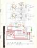
I have attached a schematic showing the readings I am getting. As you can see, they are all over the board( BTW, I took these readings with speakers connected and no input. Is that the correct method)?

The other issue I am struggling is: When I connected the 270 ohm resistor ( or any other resistor) I get a nasty hum through the speakers - as soon as I disconnect this resistor, the home goes away.

Any advice will be greatly appreciated,

-Joe Y
 

Attachments

Joe -- A number of issues. At some point, some information seems to have gotten scrambled in translation. They include:

1. At the point you show a 12K 10 watt resistor is in fact where the 270 ohm 10 watt resistor should be installed. There should not be a 12K 10 watt resistor anywhere in this amplifier.

2. At the point you show a 350 ohm 10 watt resistor is in fact where a 12K .5 watt resistor should be installed. Not sure how that got turned into requiring a 10 watt device at that point.

When you disconnect the 270 resistor (was it in parallel with the 12K 10 watt resistor you are showing?), the output stage is driven into bias cut off, so no sound would be heard. This is normal.

Your voltages are high because the output tubes cannot draw the correct amount of current unless the 270 resistor is installed.

Your hum is likely because by using a 350 ohm resistor where a 12K resistor should go, there is no effective filtering for the driver stage, so the high ripple signal is being coupled to the output stage via the plate side coupling cap, causing the hum.

Have speakers connected while taking your voltage readings.

Once you get these items straightened around, let us know how it's working then.

Dave
 
1. At the point you show a 12K 10 watt resistor is in fact where the 270 ohm 10 watt resistor should be installed. There should not be a 12K 10 watt resistor anywhere in this amplifier.

2. At the point you show a 350 ohm 10 watt resistor is in fact where a 12K .5 watt resistor should be installed. Not sure how that got turned into requiring a 10 watt device at that point.
Dave,
First off, I'd like to thank you for taking the time to share your vast knowledge with folks like me. I truly appreciate it.

My work on the 440A is not quite as messed up as it seems - I simply mis-labeled the two resistors on my diagram.

The 12K-10 watt is right where it should be (serving as R123). I don't know why I made that a 10W, but, I did. I'll change it to a .5 watt when I get a chance. For now, I don't think the excess wattage rating will impact voltage ratings. Right?

I used a 350 ohm when I didn't get the results I wanted with a 270. I have now switched it back to a 270 ohm-10 watt to help with the troubleshooting process. I never had this installed parallel to the 12k, it was installed parallel to capacitor C93-A.

That's the good news.
The bad news: I'm right back to where I was with the voltage readings. The difference between the 350 and the 270 is so small that I didn't bother to revise these on my drawing.
I still have the nasty hum when installing the 270 ohm resistor across C93-A.
I have correct the drawing (note: I did not update the voltage readings but they are very close to what is shown)

Hopefully you some more ideas for me,

Thanks,
Joe Y.
 

Attachments

Thanks for the kind words! OK, let's tackle the hum first, because the higher voltages may just be due to higher line voltages. Install the 270 ohm 10W resistor and the output tubes, but do not install the driver tubes. Turn on, and report on the hum level. If the hum is still excessive, then the power supply is the prime target. If the hum is gone, the driver stage input wiring is the next stop. Other questions:

1. Is the hum in both channels?

2. Equally?

3. Is it 60 Hz or 120 Hz (one octave higher) hum?

Let us know!

Dave
 
Ok, with no driver tubes. I get a much, much lower-volume hum, but it then complete fades away after about 60 seconds.
Putting the tubes back in, I get about the same level on both channels.
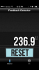
I don't have much for testing equipment, but I just downloaded this free app on my iPhone and it is telling me the hum is 236.9HZ. I dont know how much we can trust this, but I'd say it is not 60HZ.
2015-11-23 22.13.53.png

Thanks,

Joe Y.
 
Since speaker characteristics will come into play with your frequency measurement, the indication is close enough to 240 Hz which is one octave above 120 Hz -- which indicates power supply hum.

This is further supported by the fact of the hum fading away after 60 sec with no driver tubes installed: The fact that it takes 60 seconds to fade away indicates a very poor balance between the output tubes. This can be the result of either good tubes that are poorly matched, or tubes that were originally matched, but are now so worn that they are at the life point where they are all starting to go their own way as they reach the end of their life cycle. For the set to operate properly (and quietly), it requires a matched quad of output tubes to be installed, so you may want to have your tubes tested and get new ones if necessary.

However, the other issue is basic power supply filtration. The design is such that it will tolerate a certain amount of output tube imbalance without producing significant hum if the power supply is being properly filtered. This is the job of the can (filter) cap. Imbalance in the output tubes will usually occur at start up, if only because even good well matched tubes all warm at slightly different rates at turn on. But if the filter cap is bad, even well matched tubes will hum. Has the can cap been replaced in this unit yet? If not, that is the classic cause of 120 Hz hum being produced by the power supply, so that may be a next step as well -- and should be if it is still original.

Dave
 
Dave,
I have replaced the can caps. However, I am not proud of my workmanship (less than perfect soldering, inferior mounting technique, questionable location) and I have been considering a do-over. I will double check my connections and components. If I decide to re-do this work, maybe you could advise on these mysteries:
1) The new caps tend to be MUCH smaller than the old. As long as I am within uF and voltage ratings, physical size will not matter. Correct?
2) The originals were topside of the chassis and I now have them mounted below. Do I need to be concerned with shielding around the caps.
3) Most of these are available from a several manufacturers. Should I stick to one brand? Do I need to buy premium, "high-end" caps?

Thanks again,

Joe Y.
 
Joe:

As a relative newbie to tackling restorations, I think I can add a little bit to this discussion. First, take pride in the work that you do. Being self critical is a wonderful thing because you care about your final product, functionally and aesthetically. Once you get everything working as it should, you can then ponder the necessity of addressing aesthetic concerns. DO double check your connections. I'm not ashamed to say that I recently flubbed in a major way by rushing the connections to a can cap in my SA-100. Rushing and going from memory is a recipe for headache and a lot of wasted precious time. Be precise and exacting in your approach. It'll pay off in the end.

As far as your questions are concerned:

1) Modern caps are built smaller than generations of yore. If capacitance and voltage are correct, unlike some things, size doesn't matter.

2) Except for some areas in the chassis, particularly near phono circuitry and tuner circuitry, shielding is not usually a concern. If and how your leads are dressed may be. You don't want to cause an inadvertent short because of an exposed lead. Personally, if I have a slip of shrink wrap or discarded sheathing, and the location of the newly installed component suggests it MIGHT bump up against something else, I sheath it. Sometimes it's just to put good discarded material to use. Doesn't hurt.

3) Use caps that have a positive reputation over time and purchase from a reputable source. To the extent that some take the position that caps have a "sound" the conventional wisdom is to "mix em up." How much to spend is a subject that could go on for pages. It all depends on what the cap is used for. If you're replacing caps in the filtering stage, then good, reputable caps will do. A "high end" cap will work but it will not do better. On the other hand, caps in the signal chain can matter, e.g. phono stages and coupling caps. I think you're now working on the can so just use good caps that fit.

Sometimes a good, high resolution pic of what you're working on helps sort out issues. Don't hesitate because, indeed, they are worth a thousand words.
 
Last edited:
I know what helped me a lot was a photo of one of these reworked to stand alone. Let me find a picture of mine and I will post it up..
 
Agreed! About the only good thing about a Digital camera is you have instant photo's. Taking them of the unit BEFORE you start any work, from many different angles, gives you a HARD REFERENCE POINT. Then as you change things, take more pics, identifying them as to mods.

Larry
 
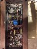
I took a picture of my 480A. This was one of the first amps I had worked on/recapped. Wow, I wasn't very good at it. I think I have gotten a little better. Lol
Hopefully this helps you as to where the resistors need to go.

image.jpg
 
It is hard to tell much from your pic, but as a general suggestion, make sure that the negative leads of all your new discrete power supply caps are grounded at the ground tabs of the old can cap. If any of them get grounded in the driver section, then ripple currents can end up flowing in the chassis, which the amplifier stages will then pick up and reproduce as hum in the output.

Some closeup pics of the power supply work would be helpful.

Dave
 
Dave,
I have replaced the can caps. However, I am not proud of my workmanship (less than perfect soldering, inferior mounting technique, questionable location) and I have been considering a do-over. I will double check my connections and components. If I decide to re-do this work, maybe you could advise on these mysteries:
1) The new caps tend to be MUCH smaller than the old. As long as I am within uF and voltage ratings, physical size will not matter. Correct?
2) The originals were topside of the chassis and I now have them mounted below. Do I need to be concerned with shielding around the caps.
3) Most of these are available from a several manufacturers. Should I stick to one brand? Do I need to buy premium, "high-end" caps?

Thanks again,

Joe Y.

Joe --- Did you ever get your 440A amp working in the stand-alone Mode? I ask, because I am looking into what is needed to make my 440A Amp work Standalone.

I found a few things on-line that might be of interest to you. The Fisher Consoles Website "www.fisherconsoles.com" has the service manual documentation for the Custom Electra Series of Consoles.
a) CE IV E-44 has the 440A paired with 440T and the tuner schematic shows there are 4 12AX7's (V8-9-10-11) in the Tuner tied to Ground and Pin #6 of the Tuner Plug,
b) CE V E-46 has the 460A paired with 460T and the tuner schematic shows there are 4 12AX7's (V8-9-10-11) in the Tuner tied to Pins #5 and #2 of the Tuner Plug.
c) CE VI E-48 has the 490A or 480A paired with 490T and the tuner schematic shows there are 3 12AX7's (V8-9-10) tied to the Tuner plug.
d) CE VII E-49 has the 481A paired with 590T and the tuner schematic shows there are 3 12AX7's (V8-9-10) tied to the Tuner plug.

So your 270 Ohm 10W resistor is probably OK for the Amps in c) and d) with 3 12ax7's in the tuner.

Your 440A should probably use something closer to 350 Ohms 10W.

If however, the CE documentation is Mislabeled for amp and tuner, all bets are off.

Please let me know your Standalone status.
Stew
 
Joe --- Did you ever get your 440A amp working in the stand-alone Mode? I ask, because I am looking into what is needed to make my 440A Amp work Standalone.

I found a few things on-line that might be of interest to you. The Fisher Consoles Website "www.fisherconsoles.com" has the service manual documentation for the Custom Electra Series of Consoles.
a) CE IV E-44 has the 440A paired with 440T and the tuner schematic shows there are 4 12AX7's (V8-9-10-11) in the Tuner tied to Ground and Pin #6 of the Tuner Plug,
b) CE V E-46 has the 460A paired with 460T and the tuner schematic shows there are 4 12AX7's (V8-9-10-11) in the Tuner tied to Pins #5 and #2 of the Tuner Plug.
c) CE VI E-48 has the 490A or 480A paired with 490T and the tuner schematic shows there are 3 12AX7's (V8-9-10) tied to the Tuner plug.
d) CE VII E-49 has the 481A paired with 590T and the tuner schematic shows there are 3 12AX7's (V8-9-10) tied to the Tuner plug.

So your 270 Ohm 10W resistor is probably OK for the Amps in c) and d) with 3 12ax7's in the tuner.

Your 440A should probably use something closer to 350 Ohms 10W.

If however, the CE documentation is Mislabeled for amp and tuner, all bets are off.

Please let me know your Standalone status.
Stew
We'll, that a whole lota info!
I did get the 440a working, but not very well. I believe I used the 270R with ok results (it's been a while and I really don't remember).
I ran into issues with hum that I did not resolve.
I also got on to quest to install individual bias adjustment pots for the output tubes, but I did complete that project.
Right now the amplifier is sitting on the shelf -waiting for me to find some and ambition .
 
The 440A was designed to work with a tuner-preamp chassis that had (4) of the 12AX7 tubes with their filaments in series as part of the cathode circuitry of the 440A output tubes. This means that 4 X 84 ohms = 336 ohms needs to be accounted for in the 440A chassis to get approximately the correct voltage to appear at the cathodes of the 6BQ5/EL84/7189 output tubes. The 350 ohm resistor mentioned is likely close enough to work as there is an adjustable "Bias" control present in the circuit too.

Make sure that C94, C95, C96 and C97 are not leaking and destroying the cathode to signal grid relative negative bias. If they are OEM caps, I would suggest you install new caps there as bad coupling caps here can damage perfectly good new output tubes.

If you want to install an on-off switch, I saw one 440A on eBay that had a toggle switch mounted on an aluminum housing directly above the 9-contact phenolic socket near the power transformer. It neatly covered up the 9-contact socket which is not being used in a stand-alone application.

Joe
 
Back
Top Bottom