• The move to the new server is done. There are some software and database maintenance updates in process. This has us passing the hat around to help out. We appreciate any donations. Seriously, even a dollar helps. The payment page may be found here - https://www.audiokarma.org/support.html

Need help with restoration onkyo m-5030

martinhajdan

New Member
Hello new to this forum and need some help, I have a onkyo m-5030 amplifier I'm restoring, my problem is finding the final four filter capacitors for this amp, They are 69v 15000mv ,I have found 80v with same mv with no problem, but there legs are only 2 and originals are 4,plus the new caps spacing for the legs are all off,If there's anyone can help i would be so grateful.
 
Register to hide this ad
Higher voltage caps are just fine, use 80V to 100V. The capacitance should be bumped up at least 10% since all the new caps being made are built about 10% below spec, don't go more than 20% over or you can have current inrush issues when you turn the amp on. An 80V or 100V and 18,000uF cap would be perfect.

First thing is you're going to have to de-solder the tick copper plates off the bottom of the board... save yourself hours of frustration and just buy a Hakko de-soldering gun-makes quick work of this task.

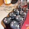
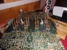
Next you will have to get some 12 gauge BARE copper wire (not clear coated for use in transformers) and make some "U"s about 1.5" long (make them the same width as the four pins on the old caps) and solder them to the legs on the cap.

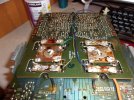
Then put in the caps and solder them to the board, then reinstall the copper plates and solder them to the copper wire legs. Finally cut them off to the proper length.

Pics are of my Onkyo M-508 so IGNORE the capacitor part numbers, but it is the same way to do a 5030/5060/506RS which are but easier- the M508 is a royal PIA to do.
5. new CDM cap wire leads 004 .jpg8. new CDM caps installation.jpg10. new copper plate fitting.JPG11. New copper plates -final.JPG
 
Last edited:
While you are in there replacing caps, don't forget to replace the relays too (99.5% sure they are about junk by now).

I also replaced the speaker jacks with new ones that take banana plus- see this thread:

 
thank you for the help,Im pretty new to restoring hifi gear and forgive me if my question sounds stupid,but i see in your pictures that you only used two legs to attach the copper wire too,you just leave the other two legs as is?
 
thank you for the help,Im pretty new to restoring hifi gear and forgive me if my question sounds stupid,but i see in your pictures that you only used two legs to attach the copper wire too,you just leave the other two legs as is?
Yes, I had to use 4 pin caps, , you only use the positive and negative legs. I snipped the other two off- put some electrical tape or silicone over these so that they don't touch anything inside the amp.
 
these relays from mouser would also be go for the m-5030
Yep, all the relays are the same for the 5030/5060/5090/506RS/504/508. You may only need two (not sure on the 5030).


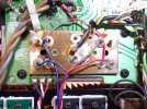
Take good pics of the wiring on the bottom of the copper plates so that you get everything back in the correct place:

main cap plate.jpg
 
Last edited:
Thanks again for all your help,do you think these would be a good replacement or bump up mv? Panasonic, 15000 uF, 80 v, 105 degree C, electrolitic capacitor,is (found it on ebay)panasonic a good capacitor to use?
 
these relays from mouser would also be go for the m-5030
Yep, all the relays are the same for the 5030/5060.5090/506RS/504/508. You may only ne two (not sure on the 5030)
Thanks again for all your help,do you think these would be a good replacement or bump up mv? Panasonic, 15000 uF, 80 v, 105 degree C, electrolitic capacitor,is (found it on ebay)panasonic a good capacitor to use?
Panasonic are fine, but STAY AWAY FROM EBAY CAPS !!! (most are fake- Buy only from Mouser or DikiKey). I would look for more capacitance- those are probably only putting out 13,500uF. Pay strict attention to the diameter (IIRC it is 40mm maximum to fit in the aluminum chanel- see pic). Look for United Chemi-Con (I have 80V 22,000uF ones awaiting install in my M-506RS) or Cornel-Dubilier (CDE).

Edit: *** I just searched Mouser and Digikey and neither have anything in stock- you'd have to order and wait 6 months (at least)***
s-l1600 (5).jpg
 
Last edited:
It wouldnt matter if the voltage is lower on those caps?Did you also change the thermal paste on the output transistors?I also see some glue connected them could this be that corrosive glue ?
 
It wouldnt matter if the voltage is lower on those caps?Did you also change the thermal paste on the output transistors?I also see some glue connected them could this be that corrosive glue ?
The rails are 52 volts, so the stock 63V would be fine (20% over which is good, and they are the only ones available, so snag them while you can). Onkyo does not use much glue at all, just a tiny dab on the main filter caps to hold them in place for soldering, and their glue is not corrosive. Vintage Sansui equipment has the issue with bad glue as they glued everything down and overflow got onto the legs of nearby resistors and corroded those. There may have been some other companies that had this issue too, but IIRC it was mainly Sansui.

Yes, I put new thermal paste on the outputs, a little goes a long way, so don't overdo it, and NEVER use conductive paste that is made for use in computers unless you want to let the magic smoke out !
 
Last edited:
Wow thanks for all your help i didnt know there where other kinds of thermal paste,i already used on two of my recievers pc paste,i guess i looks like i need to re restore my old work,thanks again for all your help....Found on a german web site i think some really good caps and free international shipping and available?https://www.it-tronics.de/en/snap-i...50c-35x80mm-esmh800vsn153ma80t-15000uf/,,,,If not at home look abroad my Hungarian mother always told me....
 
Hello can someone help me understand what are the two wires connected on output transistors with some kind of black glue,The wires are connected to the pcb with soilder and then to just two of the output transistors with glue,which is so old its not holding to the transistors
 
Hello can someone help me understand what are the two wires connected on output transistors with some kind of black glue,The wires are connected to the pcb with soilder and then to just two of the output transistors with glue,which is so old its not holding to the transistors
That is a pair of diodes that they use to sense the temperature to set the auto bias... glue them back in place just as they are... I'll find the link that explains it and post it soon.
 
Here you go (it is a M-506RS, same basic design as the M-5030- just more power)

... check to make sure you do not have the wire leading to the diode touching the transistor leg. The diode should "feel" the temp of the metal leg but not have metal to metal contact. its a thermal transfer, not "electric"


PC080148.jpg
 
Thank you for the info,is there any specific glue you would use,or is it some silicone product?
I put some Gorilla Glue Rubber Cement on mine and held it in place with a twist tie from a loaf of bread until it dried. I wasn't sure if silicone would be safe on a metal transistor leg (maybe, maybe not ?)
 
Got my new
I put some Gorilla Glue Rubber Cement on mine and held it in place with a twist tie from a loaf of bread until it dried. I wasn't sure if silicone would be safe on a metal transistor leg (maybe, maybe not ?)
Got my new caps from germany,did you have to drill holes pcb to fit those copper wires,?
 
Got my new

Got my new caps from germany,did you have to drill holes pcb to fit those copper wires,?
NO.. just bend the wires to fit the PCB... it is very easy to destroy a trace when drilling out a hole if your not very careful and you must have very sharp drill bits.
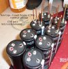
The M-5030 caps have four legs like these (pic 1) bend your new copper wires to match the spacing on the old caps (pic 2)

I wish I knew why Onkyo used such a complex design... it does make it one royal PIA to replace them ;)

109_2646.jpg5. new CDM cap wire leads 004 .jpg
 
Last edited:
Back
Top Bottom