• The move to the new server is done. There are some software and database maintenance updates in process. This has us passing the hat around to help out. We appreciate any donations. Seriously, even a dollar helps. The payment page may be found here - https://www.audiokarma.org/support.html

need repair advice denon DRA 685

RoyAbles

New Member
I recently picked up a Denon DRA 685 at the local thrift store. The problem is the left channel is dead with a hum, it's not the typical AC hum but its there none the less. The right side has sound but it's nowhere near loud enough and has the same buzz at a lower volume.
IS the unit's sound quality worth the effort to repair or take my losses and move on.
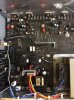
I'd like to repair myself but I've hit a wall, nothing obvious. visually everything seems in order no pregnant cap's, signs of overheating. no signal in the collector of the output tran's so i figure pre amp or input board.

ANY help would be appreciated
 
Register to hide this ad
Welcome to AK...Sounds like a power supply issue. Bad electrolytic capacitor...
 
Wouldn't happen to have a service manual,would you? Probably the closest I can get is a DRA-585. Its power supply has a good chance to be similar.
 
I wish.....got it at a thrift store rolling the dice it worked, but you are probably right. So you suspect the power supply then..... I didn't think to look there
 
Oh and i forgot to say that the base leg off the output transistors is 50v positive and negative across all 4 transistors
 
Oh and i forgot to say that the base leg off the output transistors is 50v positive and negative across all 4 transistors
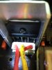
Lets hope not..The collectors should have +/- 50vdc. Center pin is the collector if it is a TO-3P output.
 
well now its making sense it is indeed the center leg is 50vdc....havent used my electronics training in 30 years and i ass-u-med it was right to left collector,base ,emitter
 
FWIW, I fixed a Denon beast AVR from about that vintage that presented a hum. It was a bad bridge rectifier. If your main caps voltage is all wonky, look to the bridge.
 
how do i know what the voltage is supposed to be on the bridge.....the bridge is loacted next to the red, orange ,yellow wire connector
 
how do i know what the voltage is supposed to be on the bridge.....the bridge is loacted next to the red, orange ,yellow wire connector
Two pins will have AC voltage and two pins will have +/- DC voltage.<--- likely +/- 50 vdc if the bridge is for the unregulated DC supply for the output transistors.And roughly 38 VAC from the power transformers secondary.( red, orange ,yellow wire connector)
 
Last edited:
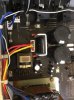
Okay, from the notch on the bridge reading left to right pin1 is 118vac, pin2 is 41vac, pin3 is 41vac, pin 4 is -51dc
orange and red wire from the master transformer has 41vac, yellow =0IMG_1088.JPG
 
If your getting stable +/- 50 vdc to the outputs. There is nothing amiss with the bridged rectifier..
 
Last edited:
Okay, from the notch on the bridge reading left to right pin1 is 118vac, pin2 is 41vac, pin3 is 41vac, pin 4 is -51dc
No way you have 118VAC on that rectifier. Your measuring incorrectly.
 
Okay, from the notch on the bridge reading left to right pin1 is 118vac, pin2 is 41vac, pin3 is 41vac, pin 4 is -51dc
orange and red wire from the master transformer has 41vac, yellow
Imprinted in the plastic right above the pins on that rectifier are symbols ( + sine sine - ) not necessarily in that order. I can't make them out in your photo.
index.php
 
Back
Top Bottom