• Please note that Audiokarma will be offline briefly for updates early on Monday morning, September 28th.

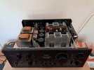
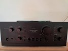
New here, first Sansui AU-719

I was pretty shocked by the disappearance of many parts that I used to purchase regularly, things are really changing in the 'new parts' world.
And it will only go worse.
In my opinion replicating the old PCBs by manufacturing new and using SMD components, as we have seen in the forum by members such Hipocrates, Tupolevfun and other is the future. Make a search on SMD components , capacitors , transistors , rectifier, Fets …etc etc , you will be surprised with the variety of what they offer along with the specs .
My 2 cents….
 
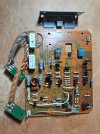
Ok so here I have a picture of one of the driver boards, with the old components removed from the board.

20250222_205610.jpg

What I found...
Firstly, a bonus for me, there was no 'Sansui Glue' on the boards!

The driver boards showed quite a difference in assembly standard, one of them had many components, resistors especially, that were not seated on the PCB correctly. And also that many resistors were not oriented the same way, normally I would expect all the tolerance or value bands to be pointing the same way. In other words in one direction for the horizontal resistors and one direction for the vertical resistors - as seen in the picture above. In good quality electronics this is done for a reason, when the boards are inspected it is much easier for the inspector to see a wrong value if (for example), the value bands all face 'right' for the horizontal resistors and 'up' for the vertical resistors. I am guessing the 2 driver boards were assembled by different workers on the production line. Now, automated assembly deals with not only the correct assembly of components and their orientation, but also automated inspection of the finished boards, before being automatically tested as well, on a 'test jig' that runs dozens of tests in a very short time.

The driver transistor screws were 'finger tight' at best, and the bias transistors were not in contact with the heatsink, I think as a result, the two driver boards had different bias and DC offset drift characteristics - which has disappeared now that the screws are tight and the bias transistors are in proper contact with the heatsink tab provided for the purpose. ;)

I didn't take a picture of the finished board, I just wanted to get it back in the unit and tested - which it now has been, result - perfect!

Now with both driver assemblies re-installed and under test.
20250223_150114.jpg

:)
 
Last edited:
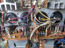
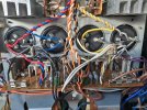
The PSU/Protector board has been taken out, stripped of old parts, repopulated with new, and is now back in the unit, everything tested and working as it should. I also replaced 7 transistors, 2SC1313 (3) & 2SA726 (3) + one 2SC945 relay driver transistor. (+ the thyristor of course - this one marked 'P0504').

There have been reports of either the speaker relay or the two large capacitors on the board preventing removal of the board downwards through the slot in the horizontal chassis. I don't remember it being an issue before, but this AU-719 needed to have those two large capacitors (2 x 470µF, 63V), removed before the board could slide out. The relay isn't a problem (despite the new relay being about 3mm taller than the old relay), and the fact that it remains below the slot in the chassis when in its final position. The relay might be a problem if extracting the board upwards, but you can only do this if you disconnect the board completely, and there is good access to the solder joints for the relay, so it can be removed if needed.

To extract the board downwards, you have to release the four main PSU capacitors from their clamps. Additionally and in this case, I had to de-solder 2 pairs of red & white wires, one grey wire (from the transformer), and 2 thick brown wires going to the mains fuse on the board. You also have to release ground tags in two positions (between the Driver modules), and the power feeds (grey & orange) to the Control Amp and Phono Boards.

Finally, while I was working on this I noticed there was a fixing nut missing from one of the transformers, it had never been there because there were no 'witness marks' on the chassis. I fitted a nut and washer even though it has survived 45 years without them. ;)
 
Last edited:
There have been reports of either the speaker relay or the two large capacitors on the board preventing removal of the board downwards through the slot in the horizontal chassis. I don't remember it being an issue before, but this AU-719 needed to have those two large capacitors (2 x 470µF, 63V), removed before the board could slide out. The relay isn't a problem (despite the new relay being about 3mm taller than the old relay), and the fact that it remains below the slot in the chassis when in its final position. The relay might be a problem if extracting the board upwards, but you can only do this if you disconnect the board completely, and there is good access to the solder joints for the relay, so it can be removed if needed.

To extract the board downwards, you have to release the four main PSU capacitors from their clamps. Additionally and in this case, I had to de-solder 2 pairs of red & white wires, one grey wire (from the transformer), and 2 thick brown wires going to the mains fuse on the board. You also have to release ground tags in two positions (between the Driver modules), and the power feeds (grey & orange) to the Control Amp and Phono Boards.
Just an FYI- On my 719 I did a recap on last year, I was able to leave the power/protect board wires all connected and pull the board up enough to have plenty of clearance to replace all the caps & clean the glue, could have replaced the relay too but mine was very clean inside and worked fine so left it alone. I did have to loosen the filter cap clamps for clearance to get the board pulled up to work on it, but it didnt need to be unhooked or completely removed, it came out fine with caps & relay in place. Just took a little ingenuity to see how it would pull out enough to work on.

Same for the phono/EQ board, was able to get access to all caps without desoldering the ribbon cable, just pulled the shafts for the knobs and unscrewed the input terminal, then the whole assembly will pull up enough to replace caps or other components.

Completely removing the boards is obviously better for best access, but for those that dont want to desolder all the wires these 2 boards can be lifted up enough to get to most parts and save time and possible problems de/re soldering stuff.
 
Last edited:
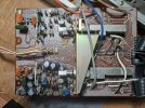
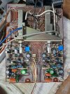
Here we have the Control Amp.

In stock condition, before removal of components.
20250225_101925.jpg


And now finished
20250225_122614.jpg

I replaced 18 capacitors with 2 of these being made redundant (and removed), due to the use of 2 single bipolars to replace 2 pairs of series connected capacitors. The switches have been checked for contact resistance, and the board is back in the amplifier all good.

So that leaves just the EQ (Phono Amp), to restore, and the main PSU filter capacitors to replace. :)
 
Last edited:
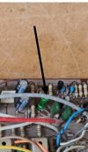
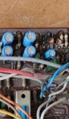
Is this single capacitor replacement, and did you install a jumper on the solder side in place of the missing cap?

View attachment 3437700

View attachment 3437701

Yep - that's it, there was a pair of output capacitors in series (to make a bipolar), difficult to see but there is a wire jumper across the other capacitor position on the component side of the board. C18 is the green (Nichicon ES), and C20 is the 'jumpered' position.
 
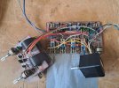
Here is the EQ or Phono Amp Board, with one channel stripped of old parts, and the other channel as original for comparison.

Oops I left the grey 47Ω resistors in - they are being replaced with metal film. ;)

20250225_210901.jpg

:)

More pictures later
 
Last edited:
The AU-719 is completed now, I am running listening tests, cleaning, and exercising the controls. :music:

This AU-719 had a parting shot at me, with a 2SA992 turning bad. Briefly on the bench I noticed some noise on the oscilloscope trace for the left channel. I made a mental note to watch for this. But later during listening tests I noticed some crackles and noise, but only with the Tone Controls engaged. So back on the bench it went, and as I had already replaced two of the three transistors, (in the Control Amp), it could only be the remaining one causing the problem, I replaced it (and its opposite number in the other channel), and all is quiet again. ;)
 
Last edited:
Back
Top Bottom