• The move to the new server is done. There are some software and database maintenance updates in process. This has us passing the hat around to help out. We appreciate any donations. Seriously, even a dollar helps. The payment page may be found here - https://www.audiokarma.org/support.html

New project: Stewart-Warner 72CR26

thorpej

AK Subscriber
Subscriber
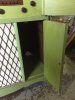
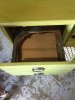
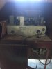
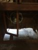
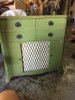
My next project is a Stewart-Warner 72CR26, a post-War (1947, I believe) AM/SW receiver with turntable. I picked it up from an estate-sale-hopping friend for $40, and plan to restore it and sell it to another friend for cost to put into her kids clothing shop (she's a big Giants fan, so hey baseball on AM radio!)

The turntable that came with it was a Garrard RC-121 Mk2. It needs considerable help -- all of the grease is sized up, but it seems in reasonable shape otherwise. I don't think the Garrard is the original turntable that came with the unit (looks more 50s-ish), and the turntable wasn't properly fastened to the drawer when I bought it.

The main chassis is a 7-tube super-het.. 6SK7 RF amp, 6SA7 detector / oscillator, 6SK7 IF amp, 6SQ7 detector / AVC, 6SJ7 AF amp (crystal phono ties in here), single-ended 6V6 output, 5Y3 rectifier. Speaker is a field-coil type with a 5.2K -> 4 ohm output transformer.

My plan is to restore the radio chassis first and get it set up in my pal's shop, and then spend some extra time restoring the turntable for installation later. (The most important thing, after all, is October baseball. The Rolling Stones come second.)

Would love to hear anyone's experience restoring this Garrard turntable... I'm OK not making the changer work and going for manual operation only, but the changer would be great.
 

Attachments
  • IMG_3737.jpg
    IMG_3737.jpg
    63.3 KB · Views: 33
  • IMG_3738.jpg
    IMG_3738.jpg
    62.9 KB · Views: 31
  • IMG_3739.jpg
    IMG_3739.jpg
    52.5 KB · Views: 31
  • IMG_3740.jpg
    IMG_3740.jpg
    52.4 KB · Views: 30
  • IMG_3741.jpg
    IMG_3741.jpg
    57.6 KB · Views: 29
  • IMG_3742.jpg
    IMG_3742.jpg
    35.7 KB · Views: 31
  • IMG_3743.jpg
    IMG_3743.jpg
    34.5 KB · Views: 30
Last edited:
Register to hide this ad
That Garrard is late 50s vintage. I had one as original equipment in a 1957 Hoffman console. I never got it to run worth a hoot and junked it in favor of an AT6. Probably could get it to go now that I have a little more experience with them but its long gone at this point. I think most of the problem with mine was a dead idler wheel, but as I recall I could never get it to run quite at the proper speed. Idler wheel usually is why it will stall or not drive at all, but this one would spin a record, just slightly on the slow side. It may have had bad motor mount grommets though. I ran into that on another older Garrard, the mounts were sagged enough that the motor pulley was out of position enough to affect the speed.
 
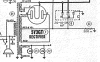
Ok, I have a slight mystery ... I replaced the power supply caps last night and installed a new 3-wire mains cord. In the process, I found a mystery lead coming from the power transformer. Attached is the relevant part of the schematic.

The power supply has a back-bias arrangement for the 6V6 output tube. I removed the leads from the original can cap and replaced them with discrete electrolytics mounted to a couple of small terminal strips that I attached to the side of the chassis. The negative leads of A, B, and C are tied together and connected to the PT secondary center tap, which is then tied to chassis ground in series with a 200 ohm power resistor. The positive leads of A and B are connected to the power rail, and the positive lead of C is connected to chassis ground.

This mystery lead was also connected to the positive lead of C on the original can... and so I think that it's possibly the grounding lead for the PT core (you can see such on the schematic), but you'll note that the schematic doesn't indicate what color this lead should be... and honestly, I have never encountered such a lead on a vintage PT before.

This mystery lead has zero continuity to ANY of the other leads on the PT (which are all accounted for, and the color indicated on the schematic). With one end of my meter connected to this mystery lead, it reads a wacky (and different) VAC against the other leads. E.g.:
  • HV 1 - 508VAC
  • HV 2 - 93VAC
  • Rectifier filament 1 - 207VAC
  • Rectifier filament 2 - 212VAC
  • Filament 1 - 202VAC
  • Filament 2 (tied to chassis ground) - 207VAC
  • Primary 1 - 202VAC
  • Primary 2 - 102VAC
Is it safe to assume that this lead is, in fact, a chassis ground reference for the PT?
 

Attachments

  • Screen Shot 2016-10-09 at 12.39.02 PM.png
    Screen Shot 2016-10-09 at 12.39.02 PM.png
    121.3 KB · Views: 8
Might be the Faraday shield ground inside. Once in a while they bring that out on it's own lead. Generally it goes to chassis. You'll get some coupling to other windings and it may read something on a high impedance voltmeter, but I expect if you took say a 100K to ground and then measured, you wouldn't get much of anything.
 
@gadget73, after getting the confirmation of my suspicion from you, I went ahead and clipped that lead to the chassis and nothing blew up. So I went ahead and made it permanent. Thanks for the sanity check.

General update -- all caps except for one extremely difficult to access .022uF cap for the oscillator have been replaced, so I went ahead and fired it up. With no antenna connected, I'm not even picking up static on either the broadcast or shortwave bands, so I'm going to have to spend some time debugging the radio section. But the AF amp works, eh, ok. I didn't expect Hi-Fi, of course, but with my iPod connected to the phono input I get some sound... needed to hose down the volume pot with Deoxit, and that helped a bit. I'm going to spend some quality time making that part work better before I get onto the radio receiver.
 
I usually use a radio to check for oscillator function. Its fairly low tech but it works.

I'm guessing the tubes and their sockets are all cleaned? A lot of the time tuners go stupid with bad connections on tube sockets. Dead tubes also will cause you grief.
 
Well, finally got back to it after being on the road for work for a few days. Once I got my 'scope on the job, it was pretty easy to find. The oscillator wasn't, and it ended up being a bad 33K screen resistor on the 6SA7. Replaced that and baseball came through loud and clear.
 
Cool. Half the time whenever I try and check oscillator function with the scope, it just shuts it down even when using the x10 probes. I can sometimes sniff around in there without actually connecting the scope but it can be annoying to find the magic spot where the probe picks up what you want to see and actually find some means of keeping it there.
 
Just finished putting it back in the cabinet and connecting the correct antenna and now it sounds absolutely fantastic. PLENTY of volume with AM stations. An iPod hooked up to the phono input is still weak sounding, in comparison, so that circuit may require some adjusting once I get the turntable working again... but that is a longer term project. Planning to drop it off at my friend's clothing shop tomorrow ... the Giants are, sadly, out of the playoffs... but she's also a Warriors fan, and they can be heard on KNBR as well :-)
 
The iPod may be looking at an impedance mismatch at the phono input...try a portable CD player or something & see what happens. I also wonder if the iPod has sufficient output to drive that input.
 
Back
Top Bottom