• The move to the new server is done. There are some software and database maintenance updates in process. This has us passing the hat around to help out. We appreciate any donations. Seriously, even a dollar helps. The payment page may be found here - https://www.audiokarma.org/support.html

New Relay, Speaker Taps, and RCA Jacks for Proton D1200. Help!

isRelative

Show Me What You Got
Hello All,

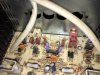
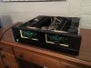
I finally got a hold of an amplifier that I've wanted for quite some time now (Proton D1200) but it needs a little work for me to make it my daily driver. It has the usual wobbly RCA jacks soldered directly to the PCB that make the sound unbalanced and/or cut in and out occasionally. One of the speaker taps is bent and I'd like to replace all 4 of them so they're not attached to that dinky PCB that doesn't really do anything. I'm not sure if I should replace the relay, but I figured I might as well if I'm doing work on it. Any suggestions as to what else I should replace?

Also, the RCA jacks are soldered to the PCB and I'm not really sure which solder points I need to heat up to remove them. I've actually never done this sort of work before so any help as to what parts I should order or how I should go about doing this would be helpful. Thanks!

Best,
Brian
Proton.jpg
 
Register to hide this ad
Any pix of the speaker and RCA jacks and PCB?

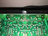
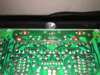
Sure do! The speaker jack replacement is fairly straightforward. I'm just going to either desolder or cut the wires from that mini PCB and attach them to some chassis-mounting speaker jacks. The RCA jacks replacement is a bit trickier because I'm not really sure which solder points are for the RCA (it should be 2 per jack for the inner/outer connection, but I only see one per jack inside the triangle made by the red/beige dots). Also, I'm unsure of what sort of wiring to use for the RCA jacks and where I should connect them on the PCB :P


IMG_0206.JPG
IMG_0210.JPG
IMG_0209.JPG
 
Last edited:
Sure do! The speaker jack replacement is fairly straightforward. I'm just going to either desolder or cut the wires from that mini PCB and attach them to some chassis-mounting speaker jacks. The RCA jacks replacement is a bit trickier because I'm not really sure which solder points are for the RCA (it should be 2 per jack for the inner/outer connection, but I only see one per jack inside the triangle made by the red/beige dots). Also, I'm unsure of what sort of wiring to use for the RCA jacks and where I should connect them on the PCB :p


View attachment 889223
View attachment 889225
View attachment 889224

Try desoldering the pads I've circled in red. It looks like the pads in the lower left of the jack pairs are the jack grounds. :
upload_2017-3-16_7-26-39.png

Picture below shows ground connection from the top.
 
Holy cow, you've got an eye for this haha. I'm assuming I'd run a wire from that ground point to the grounding sleeve and then another wire from the big center solder points to the center pins? Any idea what sort of wiring I should use? Also, these should work right?

https://www.parts-express.com/parts-express-chassis-mount-rca-jack-pair--091-1120

Those will work, but you might want to consider ones with the nut on the outside like these - that way you wouldn't have to unsolder them to remove the PCB at a later time.:
http://www.partsconnexion.com/product7496.html

This is a good place for some higher quality connectors as well - there is a pretty good sale on Cardas in the style you showed. Better connectors hold up longer and if you plan on keeping this amplifier for a while the extra ten bux or so is well worth it.
http://www.soniccraft.com/index.php/rca-chassis-c-24_72_106

Honestly, just about any hookup wire will work for short runs like this as long as it's the right diameter to solder to the PCB. I buy short lengths of teflon jacketed mil surplus wire on eBay. I usually get a white or gray jacket, then "mark" with red or white heatshrink.

Search for "24 Awg Mil Spec wire silver" or "22 Awg Mil Spec wire silver" and you can find some very nice teflon coated silver plated copper hookup wire for $6-7

Ok how are these for the RCA Jacks: http://www.soniccraft.com/product_info.php/vampire-cm2f-rca-p-1463

Around 10' of this stuff for the wiring: http://www.ebay.com/itm/NEW-M16878-4-BEB-24-AWG-Mil-Spec-Silver-Hookup-Wire-10-LENGTHS-/231662421531

For the speaker binding posts, should I go for the ones with the standard 3/4 mount like this: http://www.ebay.com/itm/Vampire-Wir...666889?hash=item53f7340449:g:xBcAAOxyaRZR0amY

Thanks for all your help guys!
 

Those will work great - Vampire makes excellent parts


Should work just fine

For the speaker binding posts, should I go for the ones with the standard 3/4 mount like this: http://www.ebay.com/itm/Vampire-Wir...666889?hash=item53f7340449:g:xBcAAOxyaRZR0amY

Also good to go

Thanks for all your help guys!

You're welcome - let us know how it turns out.
 
Those will work great - Vampire makes excellent parts


Should work just fine


Also good to go


You're welcome - let us know how it turns out.


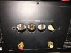
Small potential issue with the speaker jacks. I realize that the holes for the jacks are really close together. Will this pose a problem when it comes to getting enough clearance between them?

Jacks.jpg
 
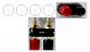
I couldn't find any dimensions for the binding posts, but used the pictures from their website for an approximation:
upload_2017-3-16_17-22-1.png
Looks to me like they will just fit. You may need to make a plate to keep them from moving around since it looks like the mounting holes for the binding posts are less than 5/8" - looks close to 1/2".
 

Attachments

  • upload_2017-3-16_17-19-27.png
    upload_2017-3-16_17-19-27.png
    144.7 KB · Views: 2
Speaking of isRelative and Proton d1200's I owe you an apology Brian. I'm sure you remember the 1200 that I sold to you a few years back. I thought for sure that you had shorted it out as it worked fine for me all those years but developed problems as soon as it arrived at your place. It turned out shipping must've disturbed the "ribbon" as that was the problem. It was an easy fix for my tech and I apologize for mistakenly assuming you'd shorted the speaker wires together.
Good luck to you with fixing your new 1200. I've decided now my 1200 is staying with me as they are great sounding amps when they're working properly.

I do remember, but no harm no foul :) I love this community too much to hold a grudge. And I know how shady some ppl can be when it comes to breaking gear and shifting the blame to someone else, so I totally get where you were coming from. Regardless though, I'm glad we both got some closure as to what really happened haha. All's well that ends well I suppose!
 
I couldn't find any dimensions for the binding posts, but used the pictures from their website for an approximation:
View attachment 889673
Looks to me like they will just fit. You may need to make a plate to keep them from moving around since it looks like the mounting holes for the binding posts are less than 5/8" - looks close to 1/2".

Hmmmm, I'm not much of a fabricator :P
 
Back
Top Bottom