• The move to the new server is done. There are some software and database maintenance updates in process. This has us passing the hat around to help out. We appreciate any donations. Seriously, even a dollar helps. The payment page may be found here - https://www.audiokarma.org/support.html

New to me 500C

KlankTank

Member
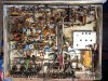
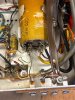
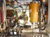
Been stalking the Fisher threads for a few months. First attempt at updating a 500C. Wired C97 first time with negative to ground but changed it to positive to ground afterword. Re-stuffed caps C97,C98 and r&r'd diodes CR7, CR5 and selenium rectifier. C97 is now getting warm/hot. Hoping you kind folks can give me a little guidance. Pics attached.
 

Attachments

  • 1.jpg
    1.jpg
    173.8 KB · Views: 48
  • 6.jpg
    6.jpg
    223.1 KB · Views: 49
  • 8.jpg
    8.jpg
    143.6 KB · Views: 47
  • 7.jpg
    7.jpg
    193.9 KB · Views: 48
Register to hide this ad
^ yeah, once they get powered backwards its iffy if the caps will still be good. I did this on a Sherwood, the one after the resistor was OK but the first one was kaput. Luckily I had ordered enough to just replace both and it was not a big deal.

also, which serial number range are we talking about here? different service manuals

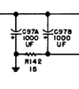
looking at the 30001+ though, it kind of looks like the can may be common negative, and the two + come out on their own terminals. At least the way its wired I don't see how it could be otherwise.

upload_2023-4-25_9-23-30.png
 
I did not put power to them until after I made the change and tied the 2 positives together to ground and one negative leg to each lug. Could something else be causing them to heat up? I only made the changes I listed above. Is it possible that the rectifier is not correct? I had 2 different kits and picked the 8A BR 1008SG over the 3A BR34.
 
Rectifier: The 8A is overkill, but won't hurt anything.
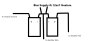
The bias caps setup is the same for the 400/ 500b/c /800b/c. Here's a drawing of how they get connected. I usually tie my negatives together thru a 2 terminal strip (without a ground) so the bias supply and the heater supply can be tied in. The positives DO NOT get tied together. One goes to ground the other goes to the Positive terminal on the rectifier. Tape the 2 caps together and insert in the clip. Squeeze clip and tie off with Zip tie to hold it in.


400 Bias Hookup.jpg
 
So, I (in)effectively put the two caps in parallel and made it a 500uf. I will ditch the idea of stuffing that cap which leaves more room for upgrades. Many thanks guys!
 
What makes the unit start "motorboating" when playing a record and the volume is turned up on the Phono stage?

motorboating is usually poor decoupling between stages. Thats a fancy way of saying that most of the time it means you have bad filter caps. Basically what happens is the signal at one stage affects the power supply which affects an earlier stage and the whole thing starts pulsing or farting or whatever.


just make sure we aren't talking about mechanical feedback from speaker to turntable though because that sounds similar but has nothing to do with the electronics. That you usually fix by isolating the two, moving them further apart is generally the first and easiest thing to try.
 
motorboating is usually poor decoupling between stages. Thats a fancy way of saying that most of the time it means you have bad filter caps. Basically what happens is the signal at one stage affects the power supply which affects an earlier stage and the whole thing starts pulsing or farting or whatever.


just make sure we aren't talking about mechanical feedback from speaker to turntable though because that sounds similar but has nothing to do with the electronics. That you usually fix by isolating the two, moving them further apart is generally the first and easiest thing to try.

When the volume goes up to around halfway, it starts this low frequency oscillation. Happens with record playing or not. Will try again with disconnected TT, then go to filter caps. Can you look at JPG.6 above and see if there is anything else obvious that you see that is funky. The unit had some work done but I am a novice at the level needed here. I wonder about the 10 ohm resistors to ground and bus wire is still connected to all 4 tubes? Are they only disconnected when doing the IBAM?
 
If its doing it with the stylus off the record, then its not mechanical feedback.

The 10 ohm resistors get added whether or not you do IBAM, it lets you monitor how much current flow is going on in the output stage. With a bias adjustment setup you can actually do something about it if things aren't happy though. In stock form they don't actually exist, there was no provision to monitor tube current.
 
Back
Top Bottom