


so it's been a while since i got new gear or posted about it. mostly just troll D Gillespie mods.. other build threads anymore but here we go.
i picked up an LK150 the other day, on one of those 'too good to be true' wow this is a really convincing scam post, posts on FB Marketplace.
there was detailed restoration information, a ton of pics and the seller actually knew what he was talking about.
turns out he's an AV engineer from Wisconsin and a really nice guy, who offered to meet me halfway, 2 hours, rather than shipping the amp.
sale price was $700. :|
i could tell from the pic, that 2 of the 6550 were USA made. turns out, they're Tung Sol.. the pair if ever sold, which they won't ever by, would run north of $500 on the bays.
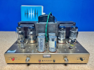
Here's the sale data:
For Sale H.H. Scott LK 150 Amplifier, 1960's Restored and modified, replaced 6550 tubes, modified capacitors and tested.contact [hidden information] More Details The Scott LK-150 model originally had two rectifier tubes in the design.
On this unit, those tube rectifiers have been replaced with solid state diodes and the holes for the two rectifier tube sockets have been covered with a metal plate.
This unit does run warm, recommendation set on a marble or stone to absorb the heat. The use of solid state diode rectifiers is a good thing. It makes the unit more reliable, generates less heat, and less noise.
Two of the 6550 tubes were replaced. The other tubes all tested fine with good output and no leaks.
Replaced the slide switch with a similar one.
The unit has four large can type, multi-capacitor, electrolytic capacitors in the center of the top of the chassis.
I left these in place physically for cosmetic purposes, but electronically, they are no longer in the circuit.
I replaced them with new, high quality axial electrolytic capacitors installed out of sightwithin the chassis.
The new caps did a better job of reducing AC ripple in the B+ power supply, which made the audio cleaner, (less residual hum).
There were a small number of other old electrolytic axial capacitors inside the chassis, all of these have also been replaced.
I also replaced the capacitors in the sub-sonic rolloff circuit with high quality new capacitors. There are four .25 mfd 600 WV coupling capacitors that tested fine.
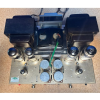
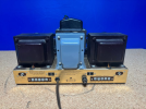

I got the amp home and hooked it up. I was blown away at how good it sounded and how well it throttled the 86db speakers I was running them with.
The mods have been done such that the amp, even with old coupling caps, still sounds impressive, thick and rich.. none of the Scott bloom that I expected, from owning the 222c, 299.. it sounds modern, fast, detailed and impactful.
TBD- I would have done the rectifier swap in the upcoming re-restoration. the last tech was a full on engineer, not an amp tech.. but imo, clearly was up to the restoration, though maybe non-standard for what I would have had my tech do..
he mounted the original power transformer above the rectifier tube spot and a new power transformer, that could handle the SS rectifier swap.. what I was told
i don't know much here. if anything I'm posting sounds technical, it was likely lifted or regurgitated from other sources.
1. swap out the .025 caps for .033.. probably something new/ nice instead of older, more traditional options..to chase 'newer' sound.
2. cut out the Lab section completely, remove the updated .047 roll-off caps entierly
3. 3 prong cord, or if space, punch out the back and install a IEC socket
-- yep, I know will ruin resale for folk who want it original. cool, never selling
4. resolder, wire everything ;D rip/ replace.
-- the 7199 sockets need looking at- left side will cut out every few hours until jiggle the tube in the socket.. will reclean but guessing there's something cold up in there
5. going to go back to cans on top, instead of underneath but that may be a phase 2, depending on how the parts in there test.
6. not sure what the mid front transformer is doing in there but I'd rather have just 2 caps for the open rectifier tube holes.
Also not trying to go crazy and dump too much $ at least right now.. my focus in any work requested will be stability and performance.. everything else will have to be post mortem and subsequent resale. There's no way I'm letting this amp go, ever. ;D
When checking bias on the 6550, they both read hot.. assuming that's partly the older caps. I was told that though caps can test good, when they're functioning they can still fluctuate.. hoping that's a good, easy fix.
The amp runs about as quiet as I've heard on a tube amp. There's absolutely no sound coming through the speakers when no signal is passing.
It does run hot but the output and power transformers are still not too hot to leave a finger on. I'm running 2 6" computer fans at the back, a few inches off, angled towards the back and focused on the transformers. there's plenty of airflow rolling under and over the transformers. IDK if this is necessary but seems smart to do, at least until recap, when the proper bias can be set.
Currently the bias knobs are turned down all the way down and still over the center meter line.
I had some RCA 7199 I wanted to try in there, to see if it voices differently. I deoxited the socket and new pins, put them back in and really liked the difference, compared to the Sylvanias.. possibly confirmation bias but I'll confirm it anyways. Post recap, those feels may change or just be confirmed. IDK.
In any event.. here's my new objet de désir.
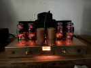
Open to any comments on the amp, work to be done, even how badly the UMG tech already ruined it ;D.. because I can learn from positivity as well as the other.
If into it, have at it
hi5
i picked up an LK150 the other day, on one of those 'too good to be true' wow this is a really convincing scam post, posts on FB Marketplace.
there was detailed restoration information, a ton of pics and the seller actually knew what he was talking about.
turns out he's an AV engineer from Wisconsin and a really nice guy, who offered to meet me halfway, 2 hours, rather than shipping the amp.
sale price was $700. :|
i could tell from the pic, that 2 of the 6550 were USA made. turns out, they're Tung Sol.. the pair if ever sold, which they won't ever by, would run north of $500 on the bays.
Here's the sale data:
For Sale H.H. Scott LK 150 Amplifier, 1960's Restored and modified, replaced 6550 tubes, modified capacitors and tested.contact [hidden information] More Details The Scott LK-150 model originally had two rectifier tubes in the design.
On this unit, those tube rectifiers have been replaced with solid state diodes and the holes for the two rectifier tube sockets have been covered with a metal plate.
This unit does run warm, recommendation set on a marble or stone to absorb the heat. The use of solid state diode rectifiers is a good thing. It makes the unit more reliable, generates less heat, and less noise.
Two of the 6550 tubes were replaced. The other tubes all tested fine with good output and no leaks.
Replaced the slide switch with a similar one.
The unit has four large can type, multi-capacitor, electrolytic capacitors in the center of the top of the chassis.
I left these in place physically for cosmetic purposes, but electronically, they are no longer in the circuit.
I replaced them with new, high quality axial electrolytic capacitors installed out of sightwithin the chassis.
The new caps did a better job of reducing AC ripple in the B+ power supply, which made the audio cleaner, (less residual hum).
There were a small number of other old electrolytic axial capacitors inside the chassis, all of these have also been replaced.
I also replaced the capacitors in the sub-sonic rolloff circuit with high quality new capacitors. There are four .25 mfd 600 WV coupling capacitors that tested fine.
I got the amp home and hooked it up. I was blown away at how good it sounded and how well it throttled the 86db speakers I was running them with.
The mods have been done such that the amp, even with old coupling caps, still sounds impressive, thick and rich.. none of the Scott bloom that I expected, from owning the 222c, 299.. it sounds modern, fast, detailed and impactful.
TBD- I would have done the rectifier swap in the upcoming re-restoration. the last tech was a full on engineer, not an amp tech.. but imo, clearly was up to the restoration, though maybe non-standard for what I would have had my tech do..
he mounted the original power transformer above the rectifier tube spot and a new power transformer, that could handle the SS rectifier swap.. what I was told
i don't know much here. if anything I'm posting sounds technical, it was likely lifted or regurgitated from other sources.
1. swap out the .025 caps for .033.. probably something new/ nice instead of older, more traditional options..to chase 'newer' sound.
2. cut out the Lab section completely, remove the updated .047 roll-off caps entierly
3. 3 prong cord, or if space, punch out the back and install a IEC socket
-- yep, I know will ruin resale for folk who want it original. cool, never selling
4. resolder, wire everything ;D rip/ replace.
-- the 7199 sockets need looking at- left side will cut out every few hours until jiggle the tube in the socket.. will reclean but guessing there's something cold up in there
5. going to go back to cans on top, instead of underneath but that may be a phase 2, depending on how the parts in there test.
6. not sure what the mid front transformer is doing in there but I'd rather have just 2 caps for the open rectifier tube holes.
Also not trying to go crazy and dump too much $ at least right now.. my focus in any work requested will be stability and performance.. everything else will have to be post mortem and subsequent resale. There's no way I'm letting this amp go, ever. ;D
When checking bias on the 6550, they both read hot.. assuming that's partly the older caps. I was told that though caps can test good, when they're functioning they can still fluctuate.. hoping that's a good, easy fix.
The amp runs about as quiet as I've heard on a tube amp. There's absolutely no sound coming through the speakers when no signal is passing.
It does run hot but the output and power transformers are still not too hot to leave a finger on. I'm running 2 6" computer fans at the back, a few inches off, angled towards the back and focused on the transformers. there's plenty of airflow rolling under and over the transformers. IDK if this is necessary but seems smart to do, at least until recap, when the proper bias can be set.
Currently the bias knobs are turned down all the way down and still over the center meter line.
I had some RCA 7199 I wanted to try in there, to see if it voices differently. I deoxited the socket and new pins, put them back in and really liked the difference, compared to the Sylvanias.. possibly confirmation bias but I'll confirm it anyways. Post recap, those feels may change or just be confirmed. IDK.
In any event.. here's my new objet de désir.
Open to any comments on the amp, work to be done, even how badly the UMG tech already ruined it ;D.. because I can learn from positivity as well as the other.
If into it, have at it
hi5
Last edited:


