• The move to the new server is done. There are some software and database maintenance updates in process. This has us passing the hat around to help out. We appreciate any donations. Seriously, even a dollar helps. The payment page may be found here - https://www.audiokarma.org/support.html

New to me SA-16...have a few questions..

Kidmoe

AK Subscriber
Subscriber
I just recently picked up a Fisher Coronet console which contained an SA-16 amp and 100-T preamp/tuner and have a few questions about the SA-16:

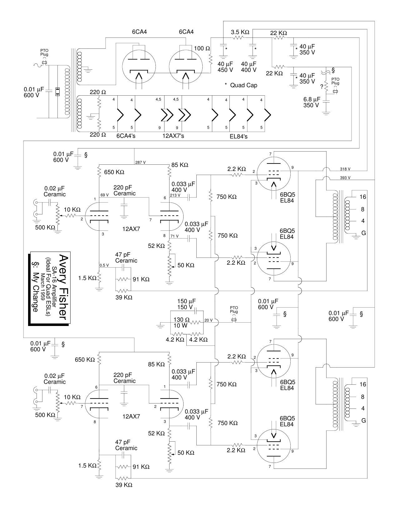
1. Can someone explain the output tube bias circuit to me? It seems as though the circuit places 7.2V on the grid and 19V on the cathode. What's the purpose of elevating the grid voltage to 7.2V? Why not just keep the grid at 0 and the cathode at 12V like most EL84 cathode biased amps seem to do?

2. How do I measure the tube bias, do I just divide the voltage across R33 by its resistance or do i have to account for the 7V at the grid somehow? With a bias resistor of 125 ohms and 19V at the cathode it would seem that the tubes are dissipating more than 12W.

3. On the schematic what are the purpose of R31 and C13, which are connected to pin 4 of the shorting plug? Are they there to support a device that could be connected to the plug? If so, can I remove them if I plan to run the amp standalone or is it fine just to leave them be?

Also, as an observation it seems to me that with only a few resistor value changes this amp is pretty much identical to the 30A amps, except the 30A don't have the same bias scheme as outlined in 1. Hope to hear from all the Fisher fans.

GvVJasa.jpg


tOTH6Rl.jpg
 
Register to hide this ad
Kid --

1. The output stage is designed so that current passing through the output tubes also passes through the heaters of the small signal audio tubes used in the connected tuner/pre (by the 7 pin socket), so that they will then operate with DC on their heaters for lowest noise. Two 12AX7s were used in the tuner/pre for the small signal amplification, and had their 12 volt heater terminals connected in series for the output stage to then supply 19 volts to. The reduced heater voltage helped to reduce noise from the tubes, and gave some room for the voltage to increase as power demands in the output stage increased (to prevent over powering the heaters) -- and all while providing enough power to the heaters for the tubes to operate properly under quiescent conditions. It's a rather narrow voltage range where this scheme works, as any less voltage and the preamp tubes won't heat properly (and output stage distortion rises), and too much could result in the preamp tubes being over powered (and the output stage to be over dissipated). In practice however, the arrangement worked very well for Fisher, as many of their designs employ this arrangement.

However, 19 volts is too much bias voltage for the output tubes to operate properly, and also wouldn't cause them to draw enough current to power the preamp tube heaters, which is what would be the case if the grids were grounded. So by biasing the output tube grids positive by 7.2 volts, it reduces the effective bias voltage to the output tubes to 11.8 volts, increasing current draw through them, and causing the cathodes of the output tubes to become elevated to 19 volts in the process. Now the output tubes are biased properly, and the preamp tube heaters are powered with enough DC voltage for them to operate properly. It's a win-win situation all around. The arrangement does have its performance limitations, but worked well enough in Fisher's lower tiered products.

2. Without a tuner/pre connected, the shorting plug must be inserted, so that R33 then takes the place of the preamp tube heaters, allowing the output tubes to operate. The shorting plug also allows AC power to be applied as well. Output tube current can then in fact be determined by measuring the voltage across R33 when the shorting plug is used. With a matched set of output tubes installed, Pd calculates to 11.58 watts per tube based on schematic information.

3. R31 and C13 provided B+ power to the tuner/pre unit. They can be removed for stand alone service.

The basic design is in fact very similar to the 30A power amplifier (bias scheme excluded), and a number of Fisher integrated amplifier designs as well.

I hope this helps!

Dave
 
Hi Dave,

No matter what I do I can’t get my SA-16 to operate properly as a stand alone power amp. It won’t put out more than a few watts without massive distortion.

Is there possibly a way to have a cathode bias circuit for each channel instead of 125 ohms for both channels (all 4 tubes having to be matched)

This thing is an absolute nightmare for me as seemingly nothing makes sense. Bias voltage (referenced to ground) at pin 2 of each of the EL84s is only a few volts at best.

No red plating but currents seem way off what they should be.

I can get a symmetrical drive of about 10V peak-to-peak out of the 12AX7 driver circuit but after that it gets funky looking.

Please let me know if you can help me!

Tom M.
 
well, we're going to hope that this schematic is accurate. Its not an original but it seems to be the only one that turns up.


Firstly do you have the shorting plug installed? It absolutely will not work correctly without it.

If you really want per-channel resistors, take the 130 ohm shared cathode resistor with the 150uF cap across it and make it 260 ohms with a 150uF cap per-channel. You will also need the two 4.2K resistors on each channel for the grid resistors to connect at the junction. 4.7K would also work fine, its not that critical, just needs to set the grid voltage to 1/2 the cathode voltage, so both need to be the same value.

If the tubes are so mismatched that they won't behave though, honestly you may really need a set anyway. Low cathode voltage implies low current flow, so either whipped tubes, or low plate or screen voltage. Screen voltage has a very significant effect on this, so you may want to see what those values are vs the schematic.

If those voltages are good, the cathode cap isn't shorted, I'm thinking your tubes are just done for.
 
That is Sheldon Stokes' schematic. From DaveG's description above the original install used some of the filaments as a load for the cathode. Sheldon shows a 130 ohm resistor. If Tom's amp came directly out of a console it may not have proper cathode biasing. Just a speculation.

@jhendrixfan can you give us a picture of the insides of your amp at decent resolution so we can take a look?
 
true but if the cathode circuit was open owing to lack of heaters or lack of that jumper plug, the cathode voltage would be very high since there is no path to ground. Very low voltage would either be straight to ground, or a much smaller than proper resistor. The plates would be glowing red in that case.

pics and voltage measurements would answer a lot of questions here. I suspect there is something other than just a cathode resistor issue here.
 
Back
Top Bottom