• The move to the new server is done. There are some software and database maintenance updates in process. This has us passing the hat around to help out. We appreciate any donations. Seriously, even a dollar helps. The payment page may be found here - https://www.audiokarma.org/support.html

New tube tester reveals I have some crap power tubes :-(

I always think to myself when I see someone bragging about the brand new, old stock, matched, RCA black plate 6l6s that they have, and how the sound is so much different (better) and that this.
How you'll never know what good music REALLY sounds like unless you use old stock tubes.
I think to myself:
Does this person own a multimeter?
Has this dude tested anything?
Or is the test, "how many likes does the image receive on socal media"
Does the amp make rated power?
What's the distortion?

This is why I stress about measuring and testing things. I've experienced on multiple occasions, amplifiers that appeared to the eyes and ears to work, but which when hooked to a scope, or investigated with a meter, I found that they did not work right at all.
 
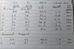
Here’s some examples of how my old Gm tester didn’t differentiate good from bad tubes. Old test values on the far right. Tube 6 is the most drastic example. IMG_8852.jpeg
 
This tester give me the Gas test results in milliAmps.
I'm sure that's not correct. My Hickok uses a scale of 0-100uA for grid current. The manual states that anything more than two microamps is undesirable and the tube should be discarded. The majority of tubes (including power tubes) don't move the meter during the gas test.

Jack
 
I'm sure that's not correct. My Hickok uses a scale of 0-100uA for grid current. The manual states that anything more than two microamps is undesirable and the tube should be discarded. The majority of tubes (including power tubes) don't move the meter during the gas test.

Jack
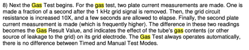
Here is the result screen. Gas on lower right. How the Amplitrex does the Gas test is shown in the second photo
 

Attachments

  • IMG_8800.jpeg
    IMG_8800.jpeg
    57.6 KB · Views: 25
  • Screenshot 2024-11-01 at 12.11.30 PM.png
    Screenshot 2024-11-01 at 12.11.30 PM.png
    132.2 KB · Views: 23
Last edited:
Here is the result screen. Gas on lower right. How the Amplitrex does the Gas test is shown in the second photo
So, it's not measuring grid current, but rather the difference (increase) in plate current that occurs when a high resistance in inserted at the grid. I would want to know a lot more about this test before discarding tubes. For example, does it use a different grid resistance for different tubes? Also, how does the test resistance for a particular tube compare to the resistance present in a typical amplifier circuit? Really, this bears further investigation.

Jack
 
So, it's not measuring grid current, but rather the difference (increase) in plate current that occurs when a high resistance in inserted at the grid. I would want to know a lot more about this test before discarding tubes. For example, does it use a different grid resistance for different tubes? Also, how does the test resistance for a particular tube compare to the resistance present in a typical amplifier circuit? Really, this bears further investigation.

Jack

Suggest you contact the manufacturer to learn more.
 
Suggest you contact the manufacturer to learn more.
I think that's your job (unless you don't mind discarding tubes that might be useful). I don't use that tester, so it's only a curiosity for me that the manufacturer chose to use that method.

Jack
 
Gordon,

This tester give me the Gas test results in milliAmps. I've not found yet in the user manual what is a good or bad gas number. From my little experience so far, all the tubes that test closed to new have gas at 1.0 mA or lower. You know what the upper spec. might be for Gas mA?

That will depend on the tester- the impedance in the grid circuit, and several other variables.

I would ask the manufacturer if they have a go/no-go spec for gas test leakage.

Regards,
Gordon.
 
I think that's your job (unless you don't mind discarding tubes that might be useful). I don't use that tester, so it's only a curiosity for me that the manufacturer chose to use that method.

Jack

Good grief Jack. I've not said a word about discarding tubes. Don't even know what a high gas number is on this tester. You have posed questions I can't answer, hence my earlier suggestion.
 
Well, thought I had word searched the complete user manual for mentions of Gas testing. Evidently got distracted and never finished that. Here is a screen capture that talks about interpreting Gas test results.

Screenshot 2024-11-01 at 4.53.13 PM.png
 
If I understand correctly, this new tester does the tube test are real world amp B+ voltages. For example, 6BQ5s are tested at 250V on the plates and it auto-biases them. There is a fixed bias mode too, but have not used that yet.

That new tester is the one I would love to have purchased, based on everything I could find as being the best tester on the market. It was to expensive for my budget, hence I went with the Maxi Matcher, which I really like as it also test tubes at operational voltages according to the manufacture. I really like the Maxi Matcher even though I would have preferred the one you have. I do have a calibrated B & K 747 for my driver tubes.
 
Grid current is measured in microamps.. Usually abbreviated as "uA" since it's hard to type "µA". 1 microamp will shift grid voltage by one volt more positive if the grid resistor is 1 megohm (it's usually lower). Most critical with high transconductance tubes like EL84, 7591, 8417, EL34 that allow high grid resistors to be used. A 6V6 or 6550 circuit can live with more grid leakage than EL84 or 7591, since lower value grid resistors must be used. And its effect varies by circuit - a Stromberg ASR-433 with 100K grid resistors will be less sensitive to grid leakage than a Fisher X-100 with 330K grid resistors.

This tester is measuring the change in plate current (mA) when the grid resistor is increased 10X (which increases the effect of grid leakage). Best measured after some warmup time as it usually gets worse with temperature. Since they don't tell you what grid resistors are (I'd guess 100K and 1 meg), it can't readily be correlated with other testers.
 
And while we're at it, grid current can be due to gas, grid emission, or contamination on the mica insulators or the glass near the pins. But the measurement and result is the same. The first cause may clear up with use (if the getter is still active), the other two will only get worse.
 
Good grief Jack. I've not said a word about discarding tubes.
No, but what else would you do with tubes that fail a gas test? It's not clear to me whether this method of indicating a gassy tube is as useful or appropriate as measuring grid current. It would be interesting to know why they elected to do it this way. I have always tested for gas by measuring grid current, and that has never failed to separate good tubes from bad.

Jack
 
No, but what else would you do with tubes that fail a gas test? It's not clear to me whether this method of indicating a gassy tube is as useful or appropriate as measuring grid current. It would be interesting to know why they elected to do it this way. I have always tested for gas by measuring grid current, and that has never failed to separate good tubes from bad.

Jack
I didn't say any tube tested failed the Gas test. Didn't even know before your prior post what a good or bad Gas mA might be on this tester. Since that post of yours, found some info in the users manual on Gas test results and shared above.
 
What criteria were you using for determining decently matched pairs when testing with your 'old' tube tester ? Ways of determining if tubes are matched seem to vary across the internet - for me I would be looking at bias voltage, and anode current and then Gm.

Looking at test results in post #22 and ignoring the emission% column - which doesn't mean a great deal - I would think that tubes 2 & 3 and 1 & 4 would be a couple of reasonably close matched pairs. This is borne out when looking at the far right column which shows Gm in uMhos. Umohs was in common use on the more up-market US made testers of the 50s and 60s, 3800 uMhos is equivalent to a Gm of 3.8 mA/Volt.

As far as your old testers agreeing with the Amplitrex it's no surprise they don't, the Amplitrex uses Gm and the old testers use uMhos, in addition I'm guessing the old testers use lower than data book voltages during the testing process, which gives lower than data book results for Gm.
There is a direct correlation between the measured Gm (which is an indicator of the 'goodness' of a tube) and the applied voltages, tube tester makers could and did test tubes at lower than data book voltages - while it is a trade-off between performance and instrument cost, it is a perfectly valid way of testing tubes - the downside is that you get results that don't agree with data book values (or modern tube testers) but instead you need the tube tester manual/databook for the tube tester makers correctly calculated values to refer to.
 
the downside is that you get results that don't agree with data book values (or modern tube testers) but instead you need the tube tester manual/databook for the tube tester makers correctly calculated values to refer to.
Not true for Hickok. Mine displays Gm in uMhos, and it agrees with data sheets for all the tubes I test. The only time I have to look in the tester manual is when an unusual tube's settings aren't in the roll chart.

Jack
 
As far as your old testers agreeing with the Amplitrex it's no surprise they don't, the Amplitrex uses Gm and the old testers use uMhos
transconductance (Gm) and is measured in uMhos. any tube tester that tests for transconductance/Gm giving results in uMhos or a conversion, of uMhos like the TV7D/U
 
Last edited:
I have long been confused by what readings on a tube constitutes a matched pair. Tubes have many different readings. Which ones are most important? I built a pair of monoblocs 40 years ago using 6BG6 tubes as finals. I run them fixed bias with a pot to adjust the grid bias. I set the bias for about 40 ma.at idle, usually winds up about -35 volts with 425 volts on the plates. The cathodes are grounded through a 5 watt, 100 ohm pot. Center to ground, each side to cathode through a break contact 1/4 inch plug. I can plug in an ammeter and adjust the 100 ohm cathode pot to achieve equal current flow through each tube. If this cannot be achieved, the tubes are not "matched". This puts the output transformer at a neutral magnetic state at zero signal. I realize that many other tube differences can and will result in a distorted output to some degree, but which ones are most important, which ones being equal would qualify that pair as "matched"? Paul.
 
Back
Top Bottom