• The move to the new server is done. There are some software and database maintenance updates in process. This has us passing the hat around to help out. We appreciate any donations. Seriously, even a dollar helps. The payment page may be found here - https://www.audiokarma.org/support.html

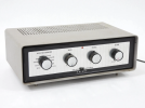
Newcomb Compact "CO-1020" Made in Hollywood CA 1955-1957

they made some with bottom connections too

View attachment 3847777

that one is an ECL82 amp but Ive seen these with 6973. No idea if they did this with a 6L6 family tube but the fronts all sorta look like this. I have a stereo preamp from this era, it also has bottom jacks.

View attachment 3847779

I just ordered an original manual from eBay.

I can use the schematic that’s inside the amp but it’s kinda of hard to see.

That and having all the caps listed out is just easier to deal with.

Still do not have any clue how to run rca jacks on it. Trying to figure out if I can re-route one to the back of the amp but that still leaves the speaker jacks. I may end up having to build some custom cables for this set.

Lastly the power cord, it’s odd it’s on a swivel so I need to figure out how to pull it apart and run a new power cable. The original one was falling apart. What’s funny is I got this one on eBay and the guy who sold it to me said it worked. He was braver than I am; I’d have never plugged that thing in with that cable. I snipped it. I do have new power cords for them so I guess that will be the 1st thing to start with.

Any advice on this unit would be great.

Now that I can see the amp section can be removed I’m almost tempted to just pull them and mounting them in wood boxes, but do I really want to destroy 50s era integrated amps.

 
I just ordered an original manual from eBay.

I can use the schematic that’s inside the amp but it’s kinda of hard to see.

That and having all the caps listed out is just easier to deal with.

Still do not have any clue how to run rca jacks on it. Trying to figure out if I can re-route one to the back of the amp but that still leaves the speaker jacks. I may end up having to build some custom cables for this set.

Lastly the power cord, it’s odd it’s on a swivel so I need to figure out how to pull it apart and run a new power cable. The original one was falling apart. What’s funny is I got this one on eBay and the guy who sold it to me said it worked. He was braver than I am; I’d have never plugged that thing in with that cable. I snipped it. I do have new power cords for them so I guess that will be the 1st thing to start with.

Any advice on this unit would be great.

Now that I can see the amp section can be removed I’m almost tempted to just pull them and mounting them in wood boxes, but do I really want to destroy 50s era integrated amps.
Leave them in the case ,it's not a magnovox.
:D
 
Put feet under it so its got clearance. Might have to drill some holes, or recycle existing screw holes so the screws are doing double duty, holding the foot and the chassis in place.

With those weird track looking features on the bottom side of the cover I wonder if this wasn't in a cabinet of some sort with a cutout to pass cables through.
 
Or make some new interconnects with some swihtcraft plugs.

That’s what I was thinking, I think for the speaker terminals I’ll make a short set of extenders connected to some nice banana plugs. Not really a fan of that but it will let me keep the original terminals and still use banana plugs.

IMG_9212.jpeg

I build interconnects all the time so that should be no problem I just need to find some that will fit.

Just need to sort out the feet.
 
Put feet under it so its got clearance. Might have to drill some holes, or recycle existing screw holes so the screws are doing double duty, holding the foot and the chassis in place.

With those weird track looking features on the bottom side of the cover I wonder if this wasn't in a cabinet of some sort with a cutout to pass cables through.

Did you see the bottom? I’ve been trying to figure out the feet. Going to see if my buddy can 3d print something for me to attach to the amp so I can try to attach some feet to them.
 
Any reason to not just use sheet metal screws through these holes?

View attachment 3848509

Yes I considered that, and tried to mount a small nut and bolt to some plastic feet but the nut on the back side of the amp comes into contact with the chassis.

Adding a sheet metal screw will do the same.

I’ll add the feet back to those slots and snap some pictures to show you what I mean.

I’d have to find a really flat screw and the bolt would need to be on the underside of the foot.

The issue is if it’s touching the chassis you can’t get the cover on properly.
 
Ok so I can’t seem to find the feet right now but the screw size I used was a 6/32. Any suggestions on one with a low profile head? I have the button top style and flush mount screws on hand but can’t really flush mount so the screws will come into contact with the chassis.

I’ll post some pic when I find where my box of feet are.

IMG_2546.jpeg

Went to de-dust this thing while I have it opened and found this ^^

Glad I didn’t power it up
 
plastic shell on a paper cap. Most of the caps in my 1953 Philco TV were cracked like this. Bumblebees in that one, but same construction. Not honestly sure if its the plastic shrinking or the paper swelling. Early plastics were not always dimensionally stable after many decades.
 
You might be able to use these.


I know another solution, but they are not cheap. And that would be adhesive mounted studs, you mount the studs with a product called click bond. It comes in either an epoxy or acrylic. You have to prep the surface well but one bonded they are very strong. They are used on aircraft and aerospace hardware often.
I have used them a lot. I don't use the nozzle on the gun to mix the adhesive as much of it is wasted in the mixing tube. I simply use a small pallet from a piece of metal and dab the two parts together and mix it with a Qtips.


I am exposed to an amazing amount of different fastener types where I work. And everything has a certification with a shelf life so once past that date it goes into the trash, or if I want it fine just take it home they can't use it.

Those actually may work, I ended up getting the schematic in on Saturday.

There is a number of smaller disc caps in the unit that I am going to leave for now.

My plan is to swap the can caps and re-work the power supply, and replace all the old PIO caps that are currently installed.

This should allow me to power them up and test them out, once I get them going Ill decided how I want to run them. as of now I am thinking of just setting the amps on some large rubber blocks i have. They are used for plant stands, and will allow me to use a 45 degree adaptor for the RCA's. For the Speaker cables. I have some vintage Radio Shack MEGACABLE the flat wound kind that I am going to solder on some spades to on one side, and some binding posts to the other. This will give me the ability to run proper banana plugs off the speaker jacks, and still keep them original.

I will try to place an order for parts this week if i have the time!
 
Back
Top Bottom