• The move to the new server is done. There are some software and database maintenance updates in process. This has us passing the hat around to help out. We appreciate any donations. Seriously, even a dollar helps. The payment page may be found here - https://www.audiokarma.org/support.html

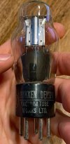
Nikken Denshi Tube ID

Jsprite7660

New Member
Hey All,

I just bought a Teisco tube amp that I'm going to restore and can't identify one of the tubes.

On the bottom is printed 29-L but I believe it's just a batch number as it's on another tube whose model number is clearly printed on the glass.

It's a 5-Pin Nikken Denshi and google lens said it's most likely a UY-76 but I wanted to post a photo here too, in case someone has seen one before.

Also, ALL of the resistors are wire-wound resistors. Any thoughts or experience coming across such a design?

I'll assume it's the UY-76 but for safe measure wanted to get a second opinion, thanks!
 

Attachments

  • Screenshot 2026-09-30 at 10.01.15 AM.png
    Screenshot 2026-09-30 at 10.01.15 AM.png
    730.7 KB · Views: 39
  • Screenshot 2026-09-30 at 10.01.06 AM.png
    Screenshot 2026-09-30 at 10.01.06 AM.png
    909.8 KB · Views: 39
  • Screenshot 2026-09-30 at 10.00.57 AM.png
    Screenshot 2026-09-30 at 10.00.57 AM.png
    801.3 KB · Views: 38
Register to hide this ad
wirewound resistors are very stable and very quiet. They do have some small amount of inductance but generally its not enough to bother anything in the audio band, but at the same time it serves as a nice stopper for RFI.


If Japanese tube numbering mirrors old US stuff, that won't be a 42. The US 42 at least is a power pentode, 6F6 predecessor I think. Unless its the 6K6 predecessor. I forget, one is a 41, the other is a 42.

A 76 is a single medium mu triode. Internal construction certainly looks right for a single indirectly heated triode.
 
Ok thank you. Yeah, it looks like the UZ-42 is a 6 pin, unless I'm reading wrong. The one I have is a 5 pin.

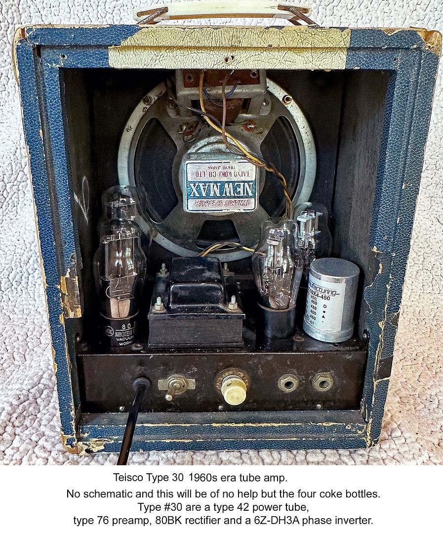
Through google lens, it says it's a Teisco Model 15 (Not to be confused with the checkmate 15). I have only seen similar "looking" amps on for sale sites when typing that in.

Here is the original ebay link to the one I bought.

And sounds good regarding the wire wound resistors, I'll leave them. New caps are on the way, and going to rewire it and add a three prong. Couldn't power on because wiring is frayed at chassis.

Going to draw out the wiring schematic just to have but it's looking like a single ended output amp which is cool.
 
My guess is a #76 tube. A five-pin single triode.

Screenshot 2026-09-30 at 10.00.57 AM - what tube.jpg
Your tube.

arcturus 76 tube.jpg
Arcturus #76 triode.

f10064ad-543d-46df-8e3f-2556f943743a.jpg


I think the caption is wrong. Mid-1950s-era combo amp. The 6Z-DH3A (diode-triode) is maybe another gain stage, or in a fixed tone stack. :idea: The amp appears to have a single-ended #42 output tube.

I could not find any schematics online. :(

Reverb link.
 
Last edited:
Hey thank you very much. I just realized that on the multi section filter cap, there's only one wire connected and on one of the other terminals a snipped remain of a wire is left, however there's no other end of it on any other component.

I'm going to just have to draw this out and come back for advice I'm guessing. Yikes
 

Attachments

  • Screenshot 2026-10-01 at 4.33.20 PM.png
    Screenshot 2026-10-01 at 4.33.20 PM.png
    741.2 KB · Views: 6
Is there a more modern looking cap somewhere? Reasonable guess that its replacing a dead section in the multi-cap if so.
 
Ahhhhh good call, there are these two "Sprague Atom 'Lytic" 8uf 500V caps as shown in the photo. The multi section is 8/8/2 at 350V. So these two could be replacing the two 8uf sections I guess.
 

Attachments

  • Screenshot 2026-10-01 at 4.57.58 PM.png
    Screenshot 2026-10-01 at 4.57.58 PM.png
    454 KB · Views: 10
Ahhhhh good call, there are these two "Sprague Atom 'Lytic" 8uf 500V caps as shown in the photo. The multi section is 8/8/2 at 350V. So these two could be replacing the two 8uf sections I guess.
Bypass the can cap altogether. Replace all with three separate axial 8mfd caps, F&T 10mfd/500VDC caps will be fine. Sprague ATOM 8mfd/450VDC will prolly work.

I'm not sure where you'd find that 2mfd cap. Probably a 5mfd will be fine. This may be the bypass cap off the #42 tube (that's just a wild guess on my part).

Good luck!
 
Ok thank you all! And yeah I ordered all new caps including a 2.2 for the 2uf section of that multi-section. Will be here Monday. Going to revise this drawn up schematic and post on here when I'm finished. I'm curious on your thoughts.

There isn't a coupling capacitor from input to the first pre amp which I thought was kinda weird and some other stuff that seems pretty weird. Will post when it's not as messy as it is now

thanks again
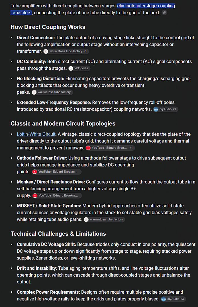
Some amps have direct coupling between stages. Two types. 1.) The cheaper end, low-powered ones (to save $ on caps), and 2.) The higher-end ones to get cleaner resolution. The higher-end ones tend to have stricter electrical parameters within each stage than amps with coupling caps, to maintain section stability.

6377f4d5-415c-4930-ac1b-2944cace129d.jpg
 
Last edited:
some things also skip the input coupling cap. In theory, its not needed since the source isn't supposed to have DC on it, but many things include one so crappy sources don't cause problems.
 
Ok cool good to know, thanks guys.

Here's what I drew up if anyone's interested. Haven't done the rectifier, power transformer or output transformer sections yet.

The two inputs have a 250K resistor across them and then to ground and the "TG" Top Grid pin of the 6C6. Attached photo of that ground terminal then a shielded cable goes up through chassis to top grid.

The plate of V3, Pin 2, feeds to the output transformer mounted on the speaker(Yellow wire in photo). And then the blue and red wire, in that same photo, are coming off of the power transformer. Photo of the power transformer as well.

Anyways, just figured I'd share.
 

Attachments

  • Screenshot 2026-10-02 at 9.51.12 AM.png
    Screenshot 2026-10-02 at 9.51.12 AM.png
    977.1 KB · Views: 6
  • Screenshot 2026-10-02 at 9.47.03 AM.png
    Screenshot 2026-10-02 at 9.47.03 AM.png
    412.5 KB · Views: 14
  • Screenshot 2026-10-02 at 9.54.42 AM.png
    Screenshot 2026-10-02 at 9.54.42 AM.png
    1,019.1 KB · Views: 13
  • Screenshot 2026-10-02 at 9.55.23 AM.png
    Screenshot 2026-10-02 at 9.55.23 AM.png
    604.5 KB · Views: 13
Looks not unreasonable, but I'd have expected a bypass cap across the output tube cathode resistor. Unless thats how they are doing feedback.

I'd rather see something coming back from the speaker secondary to probably the cathode of the 76, or plate to plate feedback between the 42 and the 76 but thats me.
 
Back
Top Bottom