• The move to the new server is done. There are some software and database maintenance updates in process. This has us passing the hat around to help out. We appreciate any donations. Seriously, even a dollar helps. The payment page may be found here - https://www.audiokarma.org/support.html

Nikko 1415 - transistor replacement

Trebolo

Member
Thanks in advance for all the help from audiokarma.org.

This thread can be a all inclusive transistor replacement list for the Nikko-1415 receiver. So i am being thorough

I am replacing the transistors on the left channel main amp board of my Nikko 1415 175wpc reciver.

The damage was severe. The outputs shorted, some transistors fried, and some resistors burned up.

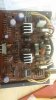
I want to replace all with new quality parts that work well together. Onsemi preferred where possible. Here is a list of the transistors and included is the schematic and some photos of the damage

I am replacing all the transistors , caps, trim pot and diodes as well as the bad resistors.

If you know of the proper replacements let me know - preferably new/readily available parts

Q701 2SA941 (BL)
Q702 2SA941(BL)
Q704 2SA941(BL)
Q705 2SA941(BL)
Q706 2SC2088(BL)
Q707 2SC2088(BL)

Q708 2SA817(O,Y)
Q709 2SC1627(O,Y)
Q710 2SD381(2) (M,N)
Q711 2SC1627 (O,Y)
Q712 2SC945 (L) (P,Q)
Q713 2SA733 (Q,R)
Q714 2SD381(2) (M,N)
Q715 2SB536 (2) (M,N)

Outputs

Q716 2SD555 (Q,R)
Q717 2SB600 (Q,R)
Q718 2SD555 (Q,R)
Q719 2SB600 (Q,R)
 

Attachments

  • nikko schematic 1.jpg
    nikko schematic 1.jpg
    179.9 KB · Views: 47
  • nikko schematic 2.jpg
    nikko schematic 2.jpg
    145.3 KB · Views: 62
  • nikko schematic 3.jpg
    nikko schematic 3.jpg
    70.2 KB · Views: 34
  • nikko schematic 4.jpg
    nikko schematic 4.jpg
    134.4 KB · Views: 53
Register to hide this ad
nikko 1415 - close up of amp schematic

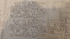
Heres a close up of the amp schematic
 

Attachments

  • nikko croped schematic.jpg
    nikko croped schematic.jpg
    168 KB · Views: 31
rebuilt nikko 1415 monster reciver - help!

Hello

I have recently completely rebuilt the left channel amp board of my Nikko 1415 receiver

I replaced all components due to a catastrophic failure of the shorted outputs and drivers , burnt resistors etc...

The previous tech had installed drivers in the VA stage that were rated at half the voltage required and possibly fake outputs.

I have replaced the parts with parts recommended by the great people on audiokarma where necessary

I have turned it on following all saftey measures and using my old variac. No smoke looks good ..... one problem so far

I check the voltage at the test points to adjust for 18.0 mv on the bias circuit
And it pulses at about 50 - 0 mv

I hooked up some speakers(test pair(cheap but good ) and i hear and see a strong pulse like a heart beat out of the side in question

Any pointers for me to check? I am applying no signal to the input as per instructions to set bias pot. And amp is not going into protect mode yet. Aslo no dc at speaker terminals

The pulse is about 700mv ac at speaker terminal

Thank You , I am sorry to place such a burden on others , but I am lost
I will post pics of finished amp as soon as finished
 
:lurk: Sounds like motor boating (Low frequency oscillation). My best guess would be one of the electrolytic caps is bad. I'd start with 711, 712 and 701. Also check grounding, and keep and eye out for errant resistor. Good luck
 
motor boating? Yes sounds that way

Can I check that with a scope. Maybe at the bias test points then at various points in the circuit before that to narrow it down

Thank You for the pointer ill be busy this thanksgiving with this. I love this type of challenge. Maybe no time for the in-laws this holiday . :D
 
Greetings;

Simple dmm check off the rails etc should show something towards the output at various points. You might consider new VR pots as I've seen in nearly all models except high end, the pots were never designed for excessive adjustments. Most of this stuff was expected to end up in a dump.

Some VR pots can be cleaned w/single drop of silicon lube a dab of alcohol and a drinking straw to blow off and some qtips to clean around, it takes a good eye and a magnifier to actually look at the pots, again simple dmm test. make sure the pot goes at least from zero to say 3/4 travel.

Further I'd just recap the schematic. Get some good caps like elna's for the audio paths in the pre and output stages and decent electrolytes for the rail paths. My bet is you'll come out on top audio quality wise as well as knowing the unit is right.

If you don't have one build a dim bulb tester for preliminary start ups. useful if you can disconnect the ps from the main boards to test a fuse blowing issue in the p.s. and your rebuild start up.
 
I noticed that when i remove the load( dummy load) the bias reading is right on and I do not measure the pulse anymore

Again that pulse is 50 - 100mv dc and about 500mv - 1.5v ac

With the load attached ( low priced speakers so i can hear it) when i probe in various locations the pulse slows way down from the 120 beats per minuet to maybe 40 -60 beats per minuet
 
Here is the schematic of the Nikko 1415

Ive replaced all components

I replaced the
Q701,702,704,705 = 2SA941 BL with 2SA970 BL
Q706,Q707 = 2SC2088 BL with 2SC2240 BL
Q708 = 2SA817 with same
Q709 =2SC1627 with same
Q710 =2SD381(2) with 2SC2073
Q711 = 2SC1627 with same
Q712 = 2sc945 with KSC945
Q713 = 2SA733 WITH KSC733
Q714 = 2SD381(2) with 2sc2073
Q715 = 2SB536(2) with 2SA940

I also replaced diodes
D701 VD1212 with 2 1n4148 in series
D702 VD1212 with 2 1N4148 in series
 
The voltage at the bases of q 714 and 715 is also pulsing hard to read but looks like 1.5v to 0

The collector voltages are correct at 69. - -69.
 
Maybe problem in current limiting part of circuit. (Q712, Q713 and associated circuits. Disconnect diodes 703 and 704, which will disconnect current limiting circuit and see if problem persists. If problem is in that area, possibilities are R733 or 734 open, or problems with 2sa733 and 2sc945 transistors. One infamous problem with those is if you use ksa733 and ksc945, make sure they are the KSC945C and KSA733C versions (They all look identical, so the only way to check is to verify collector in center and base not in center with meter or transistor checker), as regular ksc945 and ksa733 have different basing than the originals. Of course if lifting the diodes makes no difference, back to drawing board. (bad caps?) My 2 cents.
 
Why is it that with no load attached i dont see a problem
but when I add a load ( the speakers ) this happens

I have not yet placed the jumpers pre to main in yet so there is still no signal being fed to the main amp
 
Yes they are both center collector ksa733cgbu and ksc945cgta.
Is there any way this could be a bad main filter cap?

Bad filter cap would affect both channels, and usually gives loud hum, so I don't think this is the problem.
 
On the left side of your schematic it appears to be a coax line feeding the input of the power amp - check the ground on that. As you can see it is sort of isolated, for obvious reasons having to do with ground current, noise etc.

If the input ground is not grounded it could quite possibly cause such a symptom. Test by ohmmeter, but actually try jumping ground to ground anyway. An ohmmeter might not tell the truth here, depending on how the thing is built. Without the full print it is hard to tell. (maybe even with)
 
The motorboating is gone, Thank You for the help

Turns out the problem was probably a bad ground. I re soldered all parts and re tied all connections . Cleaning and sanding any possible connection point.

Now I can not adjust the Bias - The bias at the test points reads 20mv, when i first turn on, until the relay clicks and the amp is out of protect mode. Then the bias voltage drops to 1 - 2 mv But i can not adjust it. it does not respond to adjusting the 1k bias pot

The service manual call for 18mv

Also now there is a buzzing not very loud but definitely audible .

The buzzing goes away with volume down and comes back as soon as i turn volume up
 
The motorboating is gone, Thank You for the help

Turns out the problem was probably a bad ground. I re soldered all parts and re tied all connections . Cleaning and sanding any possible connection point.

Now I can not adjust the Bias - The bias at the test points reads 20mv, when i first turn on, until the relay clicks and the amp is out of protect mode. Then the bias voltage drops to 1 - 2 mv But i can not adjust it. it does not respond to adjusting the 1k bias pot

The service manual call for 18mv
Good progress

This is odd. Protection relay should have no affect on bias, unless you have DC offset problem and are connected to a load. Bias is simply measuring voltage across emitter resistors. (TP 1 is output, tp2 is one of the .47 ohm resistors going to one of the output transistor emitter. After rechecking the schematic fragment - pin 14 is not the test point - I think it's 17, but 13 works just as well (check the traces or ohm it out with power off. Careful with your ohm measurements as .47 and 0 will seem almost the same). My guess is that you are actually measuring the offset, and 14 is connected to the output when the relay closes, making the measurement go to zero.

Also now there is a buzzing not very loud but definitely audible .
The buzzing goes away with volume down and comes back as soon as i turn volume up

Sounds like more ground problems. Since affected by volume control setting, is not an amplifier but before the volume control. Is it on all inputs? both channels equal? Start checking grounds to tone control board and regulated power supplies. Keep at it - IMO this receiver is definitely worth the effort.
 
Last edited:
Back
Top Bottom