


Aldehyde
New Member
Hey everyone,
I recently assembled a Nixie tube clock kit and figured the AK crew would be interested to see the photos. I put it in the tube forum because I figured that if you like tube audio gear, you'll like Nixie tubes.
This is the inspiration. These are around $450 i believe.

Obviously, being a cheap bastard I wasn't going to spend near 500 bones on a clock, so found a kit for significantly less. I ordered it from tubehobby.com in Lithuania. It is an excellent kit and I highly recommend it.
Nixie tubes are glass tubes with numbers that light up when an electrical current is applied. They are filled with neon gas and give off a hypnotizing orange glow. They were used in the 50s and 60s before LED number displays (the red digital displays) came out. Mostly used for laboratory equipment, voltmeters, stuff like that.
For whatever reason, the USSR was huge into Nixies and produced billions of the things. There are huge stocks of surplus Nixie tubes that people have bought to use in projects, like clocks. The tubes for our clock kits are IN-14 tubes (different from those pictured in the clock above), and were made in 1981 I think.
Here is a broken nixie tube:
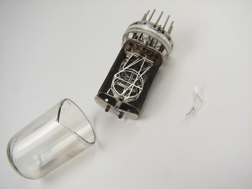

And here are the components that come in the kit: 2 PCBs and a few ICs, resistors, caps, etc.

As you'll notice, there is no case for the clock. I'll be making mine out of wood and aluminum so it will be similar to the clock above.

I have never really done an electronics kit like this before, so I reviewed online tutorials about soldering and electronic components basics (how they should be positioned, polarity, etc). Once comfortable I laid every thing out in an organized manner and set about figuring out what was what.

The components are sorta marked. Resistors have color coded bands that tell you the resistance, capacitors have the # labeled on them. Transistors have a code. The instructions are pretty good so I was able to figure it out in an hour or 2.
The PCB (printed circuit board) has the orientation of the components laid out well, so that takes most of the guess work out.
You just put each component in, solder the back, and clip the excess leads.

It is actually a lot of fun. You have to be very organized and super precise. The parts are all really small and have interesting shapes and colors. Good times.
This is a video of the same kit that I have. Mine looks the same but I didn't put in the flashing dots that separate the numbers.
http://www.youtube.com/watch?v=f4-JC8UzxTI
I recently assembled a Nixie tube clock kit and figured the AK crew would be interested to see the photos. I put it in the tube forum because I figured that if you like tube audio gear, you'll like Nixie tubes.
This is the inspiration. These are around $450 i believe.
Obviously, being a cheap bastard I wasn't going to spend near 500 bones on a clock, so found a kit for significantly less. I ordered it from tubehobby.com in Lithuania. It is an excellent kit and I highly recommend it.
Nixie tubes are glass tubes with numbers that light up when an electrical current is applied. They are filled with neon gas and give off a hypnotizing orange glow. They were used in the 50s and 60s before LED number displays (the red digital displays) came out. Mostly used for laboratory equipment, voltmeters, stuff like that.
For whatever reason, the USSR was huge into Nixies and produced billions of the things. There are huge stocks of surplus Nixie tubes that people have bought to use in projects, like clocks. The tubes for our clock kits are IN-14 tubes (different from those pictured in the clock above), and were made in 1981 I think.
Here is a broken nixie tube:
And here are the components that come in the kit: 2 PCBs and a few ICs, resistors, caps, etc.
As you'll notice, there is no case for the clock. I'll be making mine out of wood and aluminum so it will be similar to the clock above.
I have never really done an electronics kit like this before, so I reviewed online tutorials about soldering and electronic components basics (how they should be positioned, polarity, etc). Once comfortable I laid every thing out in an organized manner and set about figuring out what was what.
The components are sorta marked. Resistors have color coded bands that tell you the resistance, capacitors have the # labeled on them. Transistors have a code. The instructions are pretty good so I was able to figure it out in an hour or 2.
The PCB (printed circuit board) has the orientation of the components laid out well, so that takes most of the guess work out.
You just put each component in, solder the back, and clip the excess leads.
It is actually a lot of fun. You have to be very organized and super precise. The parts are all really small and have interesting shapes and colors. Good times.
This is a video of the same kit that I have. Mine looks the same but I didn't put in the flashing dots that separate the numbers.
http://www.youtube.com/watch?v=f4-JC8UzxTI


