
• The move to the new server is done. There are some software and database maintenance updates in process. This has us passing the hat around to help out. We appreciate any donations. Seriously, even a dollar helps. The payment page may be found here - https://www.audiokarma.org/support.html

Okay. What the heck is this DC servo stuff?

zebulon1

Retired finally and having a blast on the bench
Subscriber
I have a guys PS Audio 200cx that makes loud speaker pops and bumps when powered on and off.
I haven't checked the actual complaint but I think I see it on the DMM when checking the DC Balance.
The servo circuit is new to me and there's plenty of info in the web about it.
But:
The scats for the amp are hand drawn and missing the servo board. Reading the threads it seems PS Audio is tight with the service info.
I can make out most of the circuit and see the relationship to the servo from described web searches.

Now, How do I deal with this?
I'm thinking I have to disconnect the servo to make any DC Balance adjustments.(?)
I noticed that once the amp is warmed up the balance trimmer has no effect.
I also think I might have a bad servo amp. The servo is a separate board with an op-amp and simple circuit. The harness has four wires and is soldered to the bottom of the amp channels boards.
Note:
This amp has no protection or muting relay. Only a power on and off relay.

Below is the main amp schematic. It's all I could find so-far. No servo circuit but the output is seen near the pre stage.
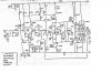
psaudio200c.jpg
 
Last edited:
Register to hide this ad
It's usually the op amps that cause those on and off thumps. At least it was with my Phase Linear 400 Series 2 amp. Can't tell if yours has any but if it bothers you, you can simply switch off the speakers at power on/off.

Never liked amps without speaker protection but I think there might be add on's somewhere out there on the web.
 
I wouldn't be at all surprised that this amps makes sounds starting up and shutting off.

Once the amp is up to speed, the servo can control it. It appears that the servo's job is only to control DC Offset (not govern feedback otherwise, and bias is set independently). Since it and the DC Offset control are dealing with controlling the input transistors, its hard to see exactly why it was thought that it was needed, but I've not actually analyzed the circuit. But what I would try doing is seeing if there is a setting on the DC Offset control that reduces the pops as it starts up and shuts off, as that's about the only time its going to have much effect. Otherwise its only function might be to balance the input devices, but those should be matched... and that might be the problem: they're no longer properly matched, perhaps due to noise, loss of gain, etc.
 
Take a look at the 33uF/25V cap on the base of the current source for the emitters of the diff pair. That should provide some delay on turn on. Try replacing it.
 
I disconnected the servo on both channels and reset the offset which is stable once it settles (I did tweak it to zero). noticing the left channel peaks high while stabilizing.
Reconnected the servos and watched both offsets and observed the left channel was very slow stabilize and will show peak voltages near 3v's.
The right is spot on with little or no voltage peaks when powering off or on.

I swapped servos and the channels performed the same, so something is up with the left channel. It does eventually settle to a near zero offset.

Take a look at the 33uF/25V cap on the base of the current source for the emitters of the diff pair. That should provide some delay on turn on. Try replacing it.
I replaced the 33/50 with new UPW's and cleaned up some previous work. It looks like someone else was looking at the same issue.
No improvement was noticed.

Connecting two DMM's to the rails shows a near perfect sync on power up and power off between the +- rail voltages, so that's good.
 
Last edited:
I swapped the JFET diff pair for curiosity with no improvement.
Something is definitely wrong with the left channel. Very sensitive to trimmer adjustment and it seems to be getting worse.

This amp is simple in design but it has a certain cheapness to it. The boards are like the Phase Linear and are easily damaged with the least amount of heat.
Plus another was in here before me. Not in a ham handed way but the circuits can only take so much work. I did put in DIP sockets to ease future work.
 
maybe the zener is flaky
I’ll check it out tomorrow. Right now I’m having a beer and thinking about how much labor is going to be in this.
The board traces and solder connections are marginal with previous work. I’m thinking about taking the board out and doing a thorough check of values, clean and reflow. I can then repaste the transistors. This approach might save some time:dunno:
This is going to be a job finding this issue.

I never tried separating the prestage from the Center rail (feedback) network. Maybe this is a good time to try it?
 
Enjoy your beer :)
I am not sure if you have a problem or not, just because one channel is behaving slightly differently at power up/down.
You have proven that both amp channels can DC balance using the jfet source balancing pot, with the DC servo disconnected
Once you hook up the DC servo, it balances to a low offset voltage again.
Correct?
The DC servo is a very low freq low pass filter, so it takes seconds to respond because you do not want it to respond to the music source, only the long term DC average.
The DC servo can be done using one or two op-amps.

Good Luck
 
I'd look for damaged traces on the board. If that's all ok, start hitting one component at a time with a small amount of freeze spray, looking for DC offset. You already proved the diff pair is ok, so do everything else on the left channel.
 
The servos are OK. The driver and output section are OK. The JFets seem off the hook as well. This doesn't leave much.

That transistor whose base is tied to the DC Offset control wiper seems to control the operating point of one of the top transistors in the cascode. The top transistors in that circuit do provide some gain. The bases are tied together so the voltage on them sets part of the operating point of the entire cascode, but if there are differences anywhere in the cascode (JFets or the top transistors) they will be exacerbated if that voltage changes. So I've become suspicious of that transistor that is setting that voltage. The CCS transistor could do it too; if its hfe is falling off the differential effect will be reduced- this can result in a voltage differential at the top of the cascode. So you have two things to look at.
 
I swapped the JFET diff pair for curiosity with no improvement.
Something is definitely wrong with the left channel. Very sensitive to trimmer adjustment and it seems to be getting worse.

This amp is simple in design but it has a certain cheapness to it. The boards are like the Phase Linear and are easily damaged with the least amount of heat.
Plus another was in here before me. Not in a ham handed way but the circuits can only take so much work. I did put in DIP sockets to ease future work.
Hmmm, sensitive to trimmer and worsening? Check everything in the red circles. And yes, I have had film caps go wonky under load causing "weird" anomalies. I am in no way familiar with any PS Audio stuff so I am just guessing here. The Servo seems to be fine as you have already discovered. As @dr*audio suggests, get out the freeze spray and monitor any, all, and even subtle changes.And definitely check all traces since they are fragile, and have been previously worked on. The "pop" smells of bad connection(s) somewhere.
psaudio200c.jpg
 
Back
Top Bottom