• The move to the new server is done. There are some software and database maintenance updates in process. This has us passing the hat around to help out. We appreciate any donations. Seriously, even a dollar helps. The payment page may be found here - https://www.audiokarma.org/support.html

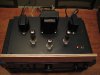
Olson/Dolly clone SE 6BQ5 build

Bloody brilliant! This might have done the trick.

One channel sounds great. The other apparently has a shorted tube - starts pulling a LOT of current when put in the socket.
 
Thanks to djnagle, I'm listening to the amp right now rather than looking at it on the "failed projects" shelf!! The people on AK who are willing to jump right in and help always amaze me! :D


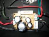
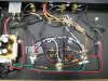
Grounding the common wire on the OTs worked. The hum was gone and the high-frequencies opened right up.

Listening right now, there is still a very small amount of hum if I put my ear right up to the speakers. It sounds like 60Hz to me...and it's pulsing. I'm thinking some tweaking of wire paths and shortening some runs will fix this.

Sounds great right now but I know some of it might be the thrill of getting the thing working at all.
 

Attachments

  • IMG_0552_800x600.jpg
    IMG_0552_800x600.jpg
    65.3 KB · Views: 25
  • IMG_0554_800x600.jpg
    IMG_0554_800x600.jpg
    115.6 KB · Views: 31
  • IMG_0556_800x600.jpg
    IMG_0556_800x600.jpg
    47.6 KB · Views: 18
  • IMG_0558_800x600.jpg
    IMG_0558_800x600.jpg
    54.5 KB · Views: 22
  • IMG_0559_800x600.jpg
    IMG_0559_800x600.jpg
    67.8 KB · Views: 27
Maybe someone with more knowledge than I could take a look at these measurements. To me they look good but I could be cooking a tube or something and, honestly, never know it.

The amp uses 1 cathode resistor for both outputs.

Voltage across the cathode resistor: 7.41v
Cathode Resistor Value: 82ohms
Works out to: 90mA across this resistor

Plate voltage is: 272v

Using 0.09(272 - 7.41) I get 23.8 watts dissipation.

This works out to 11.9 watts per tube.

If I'm understanding this correctly, these values are pushing close to the MAX for the tube but not exceeding them.
 
Glad it worked out for you willy. I am just now getting to understand tube amps so I am thrilled that my suggestion work. I built a Haggerman Octal coronet this summer and really did a great job of twisting the heater wires, and still have hum. When the thing is on and humming, I can take a wood stick and move the twisted wires and the hum goes away. I am building a 6LU8 amp next month and will twist AND use shielding on any and all paths that might cause hum. Cheers.
 
Interesting thread. Sounds a lot like my RCA console amp, the only difference is it uses a 6CA7 tube for the front end. I am close to completely rebuilding mine and viewing this thread makes me want to do it even more! :)
 
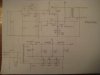
So, a few additions I made to Redboy's schematic to make this thing work:

1. Grounded common lead on secondary side of OT. (Ran the lead all the way to the speaker terminal, then another lead back to star ground.)

2. Since the 100K pot was eliminated at the input, I put a 47K resistor from input to ground. This got rid of most hum and buzz with no input attached.

3. Grounded 1 leg of the heater winding through a 150ohm resistor.

:thmbsp:
 
Here is the schematic showing the amp as it is right now.

EDIT: All 250pf caps should read 270pf.
 

Attachments

  • IMG_0560_1024x768.jpg
    IMG_0560_1024x768.jpg
    43.1 KB · Views: 44
Thanks for the schematic. Just want to be sure, are you are sharing the 6BQ5 cathode resistor and capacitor with the other channel?

Sal
 
Thanks for the schematic. Just want to be sure, are you are sharing the 6BQ5 cathode resistor and capacitor with the other channel?

Sal


Yes, pin 3 of 6BQ5 in both channels are connected together and run through a common cap/resistor to ground.
 
3. Grounded 1 leg of the heater winding through a 150ohm resistor.

Wouldn't you want to create a faux-center tap by grounding both sides of the winding via a resistor for each leg? I've also read that for maximum neurosis you can put in a pot across the winding, ground the wiper, find the optimal sweet spot, measure resistance, and replace with fixed resistors.
 
CLCLC is cap, choke,cap,choke, cap in the B+ side vs. a CRCRC which is a cap, resistor, cap, resistor, cap. I understand that the CLCLC smooths out the DC better than the CRCRC. The smoothing makes for a better sound. I am new at this so if I do not make any sense what so ever, forgive me. Cheers.
 
I grounded the other leg of the heater supply and could not hear any difference for better or worse. I also physically shielded the input jacks with a formed metal box. No obvious difference for better or worse.

There is still a very small amount of 60hz hum that is present with or without input connected and also with input shorted. You can hear it when you put your ear up to the woofer and can feel the cone vibrating slightly. Other than that the amp sounds excellent!


The smoother the DC supply, the better. How would one go about choosing values for a choke?
 
Back
Top Bottom