I’m very sorry it’s been a while since my last visit here but unfortunately I had to deal with some family problems that I wouldn’t wish anyone to happen.
Anyway…finally I got some time to open my T-9990 again and try to do some alignment.
So, the plan was to readjust “Muting Adjustment” for wide, narrow and super narrow…and set the voltage values to 0V…since my tuner couldn’t tune properly into an FM station (mainly only left tuning LED would lit even if the tuner was properly tunes into correct (any) FM station’s broadcasting frequency).
Before I started readjusting…the voltage value between:
TP1A and TP2A was…..1.854 V
TP1B and TP2B was…..3.53 V
I applied 50db…1khz signal on 99.00Mhz frequency…and I managed to adjust the voltage between TP1A and TP2A to a zero value. (I had to “turn in” the ferrite bit inside the coil L107 for around 4-5 full turns (inside direction)…to achieve 0V.
Well, that looked good…but unfortunately it wasn’t the same case with the L159.
Before starting, the voltage between TP1B and TP2B was 3.53 V. And the ferrite bit was pretty much in the middle of the L159 core.
Now, when I screw it in…almost all the way down in…there was no change in the voltage value at all. It would stay 3.53V. When I screw it out (other way…outwards direction) the voltage dropped only to 1.8 volt…and at that point the ferrite bit was almost about to drop out of the coil.
So, in other words, from one end to another…the voltage could only be adjusted between 3.53 V to 1.83 V. It wouldn’t go further down…
(On the other hand, just to point out…on L107, I was able to adjust the voltage between TP1A and TP2A…from +3.5V to -2.8 V…(that much I tried, although I believe it would probably go to more than -3.0 V)…so, not very professionally said…but both sides of the curve…plus and minus. I hope you know what I mean!
And between TP1B and TP2B…the voltage would only go from +3.53 V down to +1.83 V…never reaching zero, nor going to the other side of the curve (negative side)….so just one side of the curve.
(Just for info…that was with “+wire” of the voltmeter connected to TP1A/TP1B and “-wire” connected to TP2A/TP2B…although I thing that’s irrelevant.)
So, that obviously wasn’t a good sign…the fact that I couldn’t adjust the voltage to a “zero” V between TP1B and TP2B.
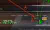
Consequently, (I guess)…the 3 tuning indicator LEDs remain in the same state…left on fully lit, the middle one (tuned)…being lit very, very faintly (picture attached)…and the right one would never lit.
Since the tuner was opened and the service manual gives the voltage values on the Q106 and Q157 (LA1235 IF section)…I thought it would be good to check them out.
I have to say…there are some big voltage differences (I’ve attached a picture)!
For example, on Q 106…on pin 12 should be 6.1V…I measured 0V (zaro) volt…! Pin 13 should be 1.5V… I measured 3.16V, pin 15 should be 0.5V…I got 0.61, pin 16 should be 0.6V…I measured 3.28V…!
On Q157…pin 7 should be 6.3V…I got 13.33 V…! Pin 13 should be 0.9V…I got 4.44V, pin 15 should be 0.4V…I got 0.61V…and on pin 16 which should have 0.5V…I measured 3.3V…!
As you can see, there are some huge differences. It certainly doesn’t seen right…and I wonder what could be the problem. Are the IF chips Q106 and Q157 faulty…? Can they change their internal characteristics that much..? Or have the surrounding semiconductors (…maybe capacitors) changed their values because of the tuners age..?
I do understand electronics to some extend…but I don’t really know how these kind of circuits exactly work…and why are the voltage values so different to the one given as a reference?
Has someone maybe got an idea what might be wrong…or what might be the problem…?
Anyway…finally I got some time to open my T-9990 again and try to do some alignment.
So, the plan was to readjust “Muting Adjustment” for wide, narrow and super narrow…and set the voltage values to 0V…since my tuner couldn’t tune properly into an FM station (mainly only left tuning LED would lit even if the tuner was properly tunes into correct (any) FM station’s broadcasting frequency).
Before I started readjusting…the voltage value between:
TP1A and TP2A was…..1.854 V
TP1B and TP2B was…..3.53 V
I applied 50db…1khz signal on 99.00Mhz frequency…and I managed to adjust the voltage between TP1A and TP2A to a zero value. (I had to “turn in” the ferrite bit inside the coil L107 for around 4-5 full turns (inside direction)…to achieve 0V.
Well, that looked good…but unfortunately it wasn’t the same case with the L159.
Before starting, the voltage between TP1B and TP2B was 3.53 V. And the ferrite bit was pretty much in the middle of the L159 core.
Now, when I screw it in…almost all the way down in…there was no change in the voltage value at all. It would stay 3.53V. When I screw it out (other way…outwards direction) the voltage dropped only to 1.8 volt…and at that point the ferrite bit was almost about to drop out of the coil.
So, in other words, from one end to another…the voltage could only be adjusted between 3.53 V to 1.83 V. It wouldn’t go further down…
(On the other hand, just to point out…on L107, I was able to adjust the voltage between TP1A and TP2A…from +3.5V to -2.8 V…(that much I tried, although I believe it would probably go to more than -3.0 V)…so, not very professionally said…but both sides of the curve…plus and minus. I hope you know what I mean!
And between TP1B and TP2B…the voltage would only go from +3.53 V down to +1.83 V…never reaching zero, nor going to the other side of the curve (negative side)….so just one side of the curve.
(Just for info…that was with “+wire” of the voltmeter connected to TP1A/TP1B and “-wire” connected to TP2A/TP2B…although I thing that’s irrelevant.)
So, that obviously wasn’t a good sign…the fact that I couldn’t adjust the voltage to a “zero” V between TP1B and TP2B.
Consequently, (I guess)…the 3 tuning indicator LEDs remain in the same state…left on fully lit, the middle one (tuned)…being lit very, very faintly (picture attached)…and the right one would never lit.
Since the tuner was opened and the service manual gives the voltage values on the Q106 and Q157 (LA1235 IF section)…I thought it would be good to check them out.
I have to say…there are some big voltage differences (I’ve attached a picture)!
For example, on Q 106…on pin 12 should be 6.1V…I measured 0V (zaro) volt…! Pin 13 should be 1.5V… I measured 3.16V, pin 15 should be 0.5V…I got 0.61, pin 16 should be 0.6V…I measured 3.28V…!
On Q157…pin 7 should be 6.3V…I got 13.33 V…! Pin 13 should be 0.9V…I got 4.44V, pin 15 should be 0.4V…I got 0.61V…and on pin 16 which should have 0.5V…I measured 3.3V…!
As you can see, there are some huge differences. It certainly doesn’t seen right…and I wonder what could be the problem. Are the IF chips Q106 and Q157 faulty…? Can they change their internal characteristics that much..? Or have the surrounding semiconductors (…maybe capacitors) changed their values because of the tuners age..?
I do understand electronics to some extend…but I don’t really know how these kind of circuits exactly work…and why are the voltage values so different to the one given as a reference?
Has someone maybe got an idea what might be wrong…or what might be the problem…?