• The move to the new server is done. There are some software and database maintenance updates in process. This has us passing the hat around to help out. We appreciate any donations. Seriously, even a dollar helps. The payment page may be found here - https://www.audiokarma.org/support.html

Onkyo TX-4500 Amp Trimmers

Warren-Oates

One Dim Bulb
Subscriber
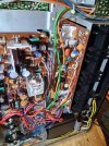
I am rebuilding an Onkyo TX-4500. At this point I have went through every board except the amp. Everything works and there has been no dimbulb issues. I have only been listening with headphones along the way. At this point I am puzzled by the trimmers on the TX-4500 amp board. There are 3 sets of trimmers; the usual bias and dc offset along with an unusual set to adjust the protect circuit (most unusual, more on that later).

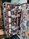
The manual mention test points CT and ID located on the amp board, the problem is I simply cannot find them. I did manage to test the DC offset by measuring on the protect board, DC Offset adjusts normally. I am attempting to test the bias before I start working on the amp board, so far I have been unable. The manual does not have a board layout image, like most manual do. Howver I will post below what I can find in the manual; instructions for adjustment and a bottom view of the amp board which appears to show a CT and ID test point.
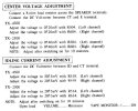
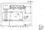
Amp_Idle_DC.JPGCTID.JPG
 
Register to hide this ad
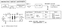
For fun here is the procedure for adjusting the protect trimmers on the amp board. I don't have a 2.5ohm 100watt dummy resistor. It sounds risky to feed a 3v 50hertz square wave into the unit and max the volume with a 2.5ohm dummy resistor attached. Am thinking I will skip this adjustment.


Protect_Adjust.JPG
 
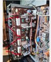
Without seeing the board layout, I would assume the leads of each emitter resistor closest to each other are connected together. So like this should work.

IMG_0828.jpeg
 
Actually I just did some testing at the emitter resistors. They are .47ohm resistors, all tested .7 with my meter, so they are good. Testing both channels as shown in Rob's photo I measured 38 volts, hmm. Testing each emitter resistor individually they were getting close to 10mv, after about 5 minutes of being on.

Measuring across one emitter I then attempted to adjust bias using VR518 and VR618, I could make the mv rise smoothly and at about 60mv I was seeing the dbt tester begin to glow, both channels adjusted in the same fashion. The bias appears to adjust normal, at least like other units I have worked on. Except it seems strange to measure full rail voltage across both of them, but both channels do it, and both channel's DC offset adjusts down to zero.
 
Normally bias is set by measurement across the output emitter resistors. I may be blind here but I'm not seeing where the test points are shown on the schematic but 20mv across 0.47 ohms is 23.5mA which doesn't seem insane to me.

By the schematic you should read zero or a few mV to ground depending on which end of the resistor you are on, and what the offset adjustment is. Not rail voltage for sure.

Three 8 ohm load in parallel is 2.5 ohms
 
At the top of the schematic I posted there is a dotted line, in it you will see E ID CT, that is the reference I mentioned.

DC offset adjusts to zero, and is fairly stable. To Ground 1 emitter resistor is rail voltage on each channel, the two resistors on the inside, but across that resistor is 10mv about. That puzzles me, but the speaker signal at the relay is 0vdc Measuring across both emitter resistors is rail volatge (as would make sense from the individual readings).

I dunno what to make of it.
 
I just found this thread on AK. Confirming the testpoints are missing from the board. And a member gives his method for setting bias.


I am into the board now, will post when I get it back together.
 
Went through the board and replaced some parts; electrolytics, 1 zener diode, the input pair transistors and the heat sensing transistors attached to the sink. For the input pair I used KSC1845 close in hfe and vbe. Q504 and 604, the heat sensors, the manual lists as 2SC945, but I found 2SC733 installed, they had glued them in and the legs were full of glue. I used KSC945C to replace them. The pre-drivers and drivers I pulled and tested, all had a gain over 70 with an atlas tester, I cleaned with a scratch pen and mounted with new compound. The four NPN outputs were pulled and tested, they all tested ok but one had lower gain than the others (only 22), so I replaced one channel's outputs with two new MJ21194.

Got it back together, I could dial DC offset to zero on both channels and I could measure across R526 & 626 and adjust for 18mv on both channels. A tiny tweak of the bias pot gets you a lot of movement, multi turn pots would have helped. With leds installed for the meters and the dial face lights the unit idles at 28 watts after being on for 10+ minutes.

It appears everything is working as it should.
 
Back
Top Bottom