


My basement rescue BIII-2 heads have little wear and playback/REC FR is excellent at +-2dB. Instead of taking a chance on a worn, used BII head block and calibration for different 2T heads, I decided to add a 4T head to my BIII-2 head block. My BIII-2 head block used the same PCB found in the BII-2 w/4T head. Otari used jumpers in place of the missing switch for the head block to center PCB ground and the 2T head R and L channel circuits.
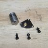
You do need some parts. The erase head needs to be moved to the end of block to follow Otari's placement. I didn't try mounting the 4T head on end to see if anything bad happens with head wrap. You get the reversible head mount for the 4T head by removing the fixed tape guide from it. (I had to heat the screw to loosen the thread lock). Due to the countersink for fixed guide screw extending under edge of head mount holes, I flipped it over and used it for the 4T head instead of erase. The washers from under the short screws for the fixed guide mount are reused for the head height/azimuth screws.
I had parts from other decks, so I had most things needed in my spare parts. You need:
Two- SPDT Switches (sourced from DigiKey, part numbers in pic)
1- 4T head
1- Head Shield (I've used one from a Teac 4010S on the BII block I mounted the Teac 4T head (different mounting required drilling additional holes in mount. I also had to drill a hole in shield for lower head height screw)
7"/177mm 2mm thin Coax (cut in half for two). I only had black, so I added some red and brown shrink on each end to match coax color Otari used.
Two- M2 x 5mm head mount screws
Two- M2 lock washers
Two- M2 flat washers
Two- M3 x 12mm black Allen head screws for height (or three if you don't care if the azimuth adjust is black, or paint one silver)
One- M3 x 12 Silver Allen head screw for azimuth adjust
Three- Head adjust springs. I had two different styles from a Teac 4010S. Straight wall were 4.8mm diameter x 4.5mm in length.
The OEM switch is an open at each end 4PDT. The one in my BII block was heavily oxidized. You don't need a 4 pole. Following Tapetech's advice, I wanted a sealed switch with gold contacts. A DPDT would work but I couldn't find one with close pin spacing. I used two SPDT gold contact switches instead. I had to carefully tweak the terminals without breaking rear of switch to fit hole spacing and mount them side by side. I bent the outer strain relief switch mount pins 90 degrees and cut off the inner ones.
I'm just a hobbyist, not a tech. I believed the OEM switch housing acted as a shield for the contacts, so I made a shield out of thin aluminum to cover the exposed terminals/bottom of switch. Never tried it without, so maybe it's optional and a waste of my time. Aluminum requires special methods to solder so I covered it with some adhesive copper foil tape I had. I used some tinned bare hook up wire to connect the head block grounds on both sides of switches to center PCB ground just like the OEM switch housing did. I soldered them to the copper foil at front and rear and the strain relief terminals at each end of switches. The head ground end uses a star washer between pcb and block mount.
I used a new 4T head in 2T body off ebay. The one Tapehead member Twinimage came up with ~2018. In one ad for 2T heads the description read they were made by the same company that supplied the later design Otari heads after the first supplier closed their doors. Twinimage must be Roman Sokolov of Electronic Engineers, an analog audio repair shop in Chicago. His wife sells them on ebay, user name sewing-pro. No affil other than buyer.
A digital microscope helps my old eyes with initial tape edge alignment. The head needs to be adjusted a bit more until edge of tape hits the copper color laminate. The Sharpie test with old tape for head wrap done on deck along with azimuth. I had a spare set of BIII tape guides attached to headblock for easier off the deck initial alignment. The ones on my BIII are thread locked and I don’t want to mess around heating them to remove.
I thought about cobbling something together or having something 3D printed to connect both switches together, but don't mind having to move two switches to choose between 2T/4T play heads.
Attachments
-
 biii block wo4t.jpg52.8 KB · Views: 20
-
 headcoversm.jpg136.6 KB · Views: 25
-
 optical_setupsm.jpg246.6 KB · Views: 17
-
 sheilds.jpg116.7 KB · Views: 18
-
 shield_sm.jpg151.7 KB · Views: 13
-
 ck_spdtx2sm.jpg115.1 KB · Views: 12
-
 oem_markedsm.jpg119.5 KB · Views: 13
-
 biii_4t_mount.jpg176 KB · Views: 13
-
 guide.jpg246.1 KB · Views: 13
-
 needsm_holeshield.jpg171.4 KB · Views: 20
Last edited:


 Pics in my other thread.