• The move to the new server is done. There are some software and database maintenance updates in process. This has us passing the hat around to help out. We appreciate any donations. Seriously, even a dollar helps. The payment page may be found here - https://www.audiokarma.org/support.html

Pair of Dynaco Mark IV buzz. SOLVED

are you looking at the Mark IV voltage chart ? Thats for a 7199, and the pins are arranged differently. I think I misunderstood how you posted it, if this is the amp on the left and what the book says on the right, its not going to match. This is the pinout difference marked up in 6GH8 / 7199 format.

  • 290 280 - triode plate / triode plate
  • 140 -71.2 mv pentode grid / pentode plate
  • 42 34.3 pentode screen / pentode screen
  • – heater / heater
  • – heater / heater
  • 1.5 108.5 pentode plate / pentode cathode
  • – pentode cathode / pentode grid
  • 145 115 triode cathode / triode cathode
  • 140 108 triode grid / triode grid
 
So after being enlightened on the fact that I mid read the voltage chart it looks like my GZ34 and the EL34s are doing what they are supposed to be doing. All voltages are correct.

The issue now seems to be pin 2 and 6 of the 6GH8. Pin 2 should be 140 DC and I get -71.2 Mc and a loud buzz. Pin 6 should be 1.5 DC and I get 108.5 DC
pin 2 is the g1 and should be close to zero. Pin 6 is the plate and seems correct.
The pin numbers in the manual refers to 7199 and is not the same as 6gh8 !

Your problem is "buzz" from the filament windings. To convince yourself, get a DC source of app 6v, and
conect to lugs 4 & 5 on the circuit board ( follow the trace to see that they go to pin 4 & 5 on the 6gh8 tube)
When the 6gh8 filament is powered by DC all your buzz is gone. This is not your final solution however as
it is unpractical to have an external DC source.

Ways of reducing the buzz is :
- other tubes
- elevation of all filaments
- arrange a DC feed. Could be done with a bride rectifier and som caps. Note that you might need a resistor in
series since rectified 6.3V will give app 8VDC.
 
are you looking at the Mark IV voltage chart ? Thats for a 7199, and the pins are arranged differently. I think I misunderstood how you posted it, if this is the amp on the left and what the book says on the right, its not going to match. This is the pinout difference marked up in 6GH8 / 7199 format.

  • 290 280 - triode plate / triode plate
  • 140 -71.2 mv pentode grid / pentode plate
  • 42 34.3 pentode screen / pentode screen
  • – heater / heater
  • – heater / heater
  • 1.5 108.5 pentode plate / pentode cathode
  • – pentode cathode / pentode grid
  • 145 115 triode cathode / triode cathode
  • 140 108 triode grid / triode grid
I was referred to the Dynaco voltage chart by the Dynakit people who made this PC4 board. This is a 6GH8 board and my understanding is that the way it is built it should match the voltage chart?
 
voltages will be similar, but the pin order will not be the same. If you match it for function it will line up but the pentode grid won't have the same voltage as the pentode plate.

so for example on pin 2, 140 makes sense for a pentode plate, and basically zero makes sense for the grid.
 
voltages will be similar, but the pin order will not be the same. If you match it for function it will line up but the pentode grid won't have the same voltage as the pentode plate.

so for example on pin 2, 140 makes sense for a pentode plate, and basically zero makes sense for the grid.
The problem is I am not getting 140 on pin 2... I get -71.2 mv.
 
The problem is I am not getting 140 on pin 2... I get -71.2 mv.
That's not a problem, it's a measurment thing. I would not care.

Your problem is in the filament that bleeds through the filament<>cathode surface in the tube.
 
are you looking at the Mark IV voltage chart ? Thats for a 7199, and the pins are arranged differently. I think I misunderstood how you posted it, if this is the amp on the left and what the book says on the right, its not going to match. This is the pinout difference marked up in 6GH8 / 7199 format.

  • 290 280 - triode plate / triode plate
  • 140 -71.2 mv pentode grid / pentode plate
  • 42 34.3 pentode screen / pentode screen
  • – heater / heater
  • – heater / heater
  • 1.5 108.5 pentode plate / pentode cathode
  • – pentode cathode / pentode grid
  • 145 115 triode cathode / triode cathode
  • 140 108 triode grid / triode grid
On the chart you just made The Dynaco voltage chart numbers are on the Left and my amps 6GH8 readings are on the Right.
I apologize If I wasn't clear.
 
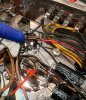
The green/yellow tap goes to this 5 lug terminal strip the central lug is ground but the lug the g/y is soldered too goes nowhere?
 

Attachments

  • 68B310B3-337A-47DF-ADFE-54C3CF20F135.jpeg
    68B310B3-337A-47DF-ADFE-54C3CF20F135.jpeg
    175 KB · Views: 14
index.php
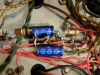
I see on this random photo from the internet (which was another MK IV thread on AK) that the that the green/yellow from the transformer has a jumper lead to ground and mine doesn't.
 

Attachments

  • MK IV bias terminal strip. .png
    MK IV bias terminal strip. .png
    849.5 KB · Views: 15
If you have an ohm meter, measure from one of the green filament wires to chassis. If it reads a very low resistance, less than 1 ohm, then you have a good ground connection somewhere. If it's some high resistance, then no. If the green/yel wire in your amp isn't somehow connected to chassis common, then that might very well be your noise problem. Or, at least one of them.
John
 
I am seeing multiple images where the green/yellow center tap of the transformer is either jumpered to the ground tap or soldered directly to the ground tap of the terminal strip. Is this a build issue on my amps?
 
If you have an ohm meter, measure from one of the green filament wires to chassis. If it reads a very low resistance, less than 1 ohm, then you have a good ground connection somewhere. If it's some high resistance, then no. If the green/yel wire in your amp isn't somehow connected to chassis common, then that might very well be your noise problem. Or, at least one of them.
John
It looks like both my amps are wired this way and everyone I see has a jumper or is soldered to the middle (ground) terminal of that 5 lug strip...

I will check the green to chassis this evening. Thanks for the suggestion.
 
On the chart you just made The Dynaco voltage chart numbers are on the Left and my amps 6GH8 readings are on the Right.
I apologize If I wasn't clear.

if thats the case I think you're fine. The grid is pretty close to zero volts as it should be.
 
The green and yellow tap from the transformer currently goes to its own lug on the 5 lug bar where all the bias bits are.
That connection should be grounded.
The issue now seems to be pin 2 and 6 of the 6GH8. Pin 2 should be 140 DC and I get -71.2 Mc and a loud buzz. Pin 6 should be 1.5 DC and I get 108.5 DC
Please review the info posted above regarding the difference in pin numbering. You're on a wild goose chase. The buzz has nothing to do with these voltages.
 
That connection should be grounded.

Please review the info posted above regarding the difference in pin numbering. You're on a wild goose chase. The buzz has nothing to do with these voltages.
You are correct. I ran home over lunch and grounded the g/y and the buzz is gone.
 
I ran home over lunch after Kevin from Dynakit confirmed that the green/yellow from the transformer should indeed be grounded not just soldered to the terminal strip all by itself!
I used an insulated jumper and ground the terminals and it is quieter than I expected.
I have quiet amps!
 

Attachments

  • 4A38719E-01DB-44D5-A2E6-EC074873DCEE.jpeg
    4A38719E-01DB-44D5-A2E6-EC074873DCEE.jpeg
    115.5 KB · Views: 32
I ran home over lunch after Kevin from Dynakit confirmed that the green/yellow from the transformer should indeed be grounded not just soldered to the terminal strip all by itself!
I used an insulated jumper and ground the terminals and it is quieter than I expected.
I have quiet amps!
Congratulation. What happened was that the filament "drifted" in DC , probably due to small polarity sensitive
rectification in the filment/cathode space.
 
Excellent! And it seems you probably won't have to elevate the filaments after all.
Not that I was going to avoid learning how but I really felt it was a problem caused by the previous owner. Now I have a good baseline. if I decide to tweak.
 
Back
Top Bottom