• The move to the new server is done. There are some software and database maintenance updates in process. This has us passing the hat around to help out. We appreciate any donations. Seriously, even a dollar helps. The payment page may be found here - https://www.audiokarma.org/support.html

Parasitic oscillation?

ocdecio

The proof of the restoring is in the listening.
Subscriber
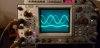
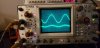
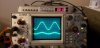
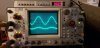
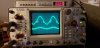
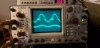
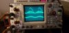
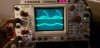
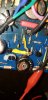
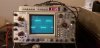
After rebuilding the left channel on a 1200, I finally was able to get some bias (connected to the DBT). However as soon as bias start to inch up, the output waveform gets all distorted. When I turn it off, for some seconds the waveform cleans up before fading away.

Have anyone seen this behavior? I replaced most capacitors on this board so I am at a loss as to what to do.
 

Attachments

  • 20210419_192908.jpg
    20210419_192908.jpg
    72.5 KB · Views: 31
  • 20210419_192918.jpg
    20210419_192918.jpg
    73.8 KB · Views: 30
  • 20210419_192920.jpg
    20210419_192920.jpg
    76.7 KB · Views: 29
  • 20210419_192925.jpg
    20210419_192925.jpg
    73.4 KB · Views: 29
  • 20210419_192930.jpg
    20210419_192930.jpg
    74 KB · Views: 27
  • 20210419_192937.jpg
    20210419_192937.jpg
    71.2 KB · Views: 28
  • 20210419_192942.jpg
    20210419_192942.jpg
    71.2 KB · Views: 29
  • 20210419_192950.jpg
    20210419_192950.jpg
    69.2 KB · Views: 27
  • 20210419_192955.jpg
    20210419_192955.jpg
    69 KB · Views: 28
  • 20210419_192959.jpg
    20210419_192959.jpg
    58.4 KB · Views: 31
Register to hide this ad
After rebuilding a Sansui 9090 driver board, which had missing transistors, I had rail to rail oscillations at high freq. Blew out the tweeters on my test speakers! Finally figured out I had to run the bias higher than the adjustment in the SM to keep that from happening.

I don't recall if the one 1200 I worked with had an issue with running on a DBT. Do you have a variac so that you can skip the DBT?
 
After rebuilding a Sansui 9090 driver board, which had missing transistors, I had rail to rail oscillations at high freq. Blew out the tweeters on my test speakers! Finally figured out I had to run the bias higher than the adjustment in the SM to keep that from happening.

I don't recall if the one 1200 I worked with had an issue with running on a DBT. Do you have a variac so that you can skip the DBT?

Well I guess this is a great excuse to get one. DBT is good to find shorts but it may be messing up and maybe generating oscillations.

I may need a wattmeter too, right? Thank you!
 
Nah on the wattmeter. Too iffy of a method to me! I looked through my 1200 and 1200B folders but danged if I didn't jot down what I did to adjust bias. Could be I started by turning it CCW with an eye on the AC line current meter in my variac/DBT setup until the current stopped going down and then brought it up just a little bit. I think that amp's power out is like 75 watts or maybe a 100? If it's stable after doing the bias adjustment on both sides I'd monitor the heatsink temp on both sides for warmth like other amps in that power range and monitor the (bias) voltage across an emitter resistor or both.

Of course you could monitor the AC line current and just do the math too. I saw something about 40 watts which would be 0.33 amp at 120 volts. That may have been an upper limit on current at no signal too. Anyway, was it 10 watts more they say to bring it up? So the would be 10/120 more current or 83.3 mA.
 
@rBuckner my concern with the variac as opposed to the DBT it that fear the risk of bias getting too high or the amp start oscillating badly and blowing stuff up. In your experience, when do you feel safe to trust the amp won't get in such trouble? I am pretty sure I don't have any shorts or components installed backwards. And yes, this is a 100WPC model.sharing one of the versions of amplifier board used in the 240/250 models.
 
On a working unit of this model it shouldn't go into oscillation. But yours isn't working right of course so my method would be a risk.
 
On a working unit of this model it shouldn't go into oscillation. But yours isn't working right of course so my method would be a risk.
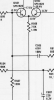
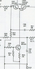
Very true. There is something odd with its DC balance as well that is getting affected by the bias adjustment. I converted it from MK1 to MK2 so to speak following the Addendum and one thing I didn't do yet was converting the long tail emitter resistor into a current source, which I believe is what's happening here:

From:

upload_2021-4-20_10-58-24.png


To:

upload_2021-4-20_10-58-10.png

Maybe this could be related to stability. Until I am able to make this unit show a clean waveform I think it will be safer to stay with the DBT.
 
Last edited:
giphy.gif

Bias set, amp off the DBT. I followed mostly all steps outlined in the Addendum, except replacing the bias trimpot which I will see how best to do it.

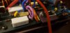
I had to cut traces to install 5.6ohm resistors at the driver emitters, add the kludge on top of the 39ohm resistor and another kludge to add a current source to the diff pair,

Diff pair is now 2N5089 with hFE of 830. I didn't connect speakers yet, hope won't blow them up!
 

Attachments

  • 20210420_200537.jpg
    20210420_200537.jpg
    41.8 KB · Views: 28
  • 20210420_200523.jpg
    20210420_200523.jpg
    84.2 KB · Views: 27
  • 20210420_200004.jpg
    20210420_200004.jpg
    72.9 KB · Views: 26
Cool! So the oscillation is gone? I assume you rechecked the bias after getting off of the DBT, right? :biggrin:
Yes, it became much better after inserting Q520 (MPSA20) as the diff pair current source and the higher hFE for the diff pair. I took it off the DBT and got a clean wave above 12mv.

Now I am battling a vexing issue - I probably have a cold joint where the transistor and diode connect to the three posts on the board because if I slam the table or wiggle the transistor wires the bias and the output go bezerk. I'll have to disassemble everything including the inductor and see if I can get a good connection to the posts - a task that is revealing difficult to do properly but I'll have to do it.
 
Yes, it became much better after inserting Q520 (MPSA20) as the diff pair current source and the higher hFE for the diff pair. I took it off the DBT and got a clean wave above 12mv.

Now I am battling a vexing issue - I probably have a cold joint where the transistor and diode connect to the three posts on the board because if I slam the table or wiggle the transistor wires the bias and the output go bezerk. I'll have to disassemble everything including the inductor and see if I can get a good connection to the posts - a task that is revealing difficult to do properly but I'll have to do it.

So what did you do with board modifications? Did you add in the MPSA6519 to the bias Circuit or forgo that? Just curious...

I am almost certain my board revision on the 250 has the driver emitter resistors as I was measuring them the other day...
 
So what did you do with board modifications? Did you add in the MPSA6519 to the bias Circuit or forgo that? Just curious...

I am almost certain my board revision on the 250 has the driver emitter resistors as I was measuring them the other day...
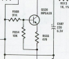
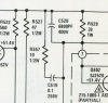
I followed all instructions in the Addendum:

1. Replace R508 7.5k with MPSA20 current source circuit

upload_2021-4-21_18-8-47.png

2. Install R527, R557, C520 on top of R329 39Ohm (the first klugde/abomination you asked about)

upload_2021-4-21_18-9-3.png

3. Replace various resistor and capacitor values in the signal path

4. Replace diff pair with 2N5089 (hFE = 830)

That seems to be a good path. I am chasing down a cold joint somewhere but if I let the amp undisturbed, I can get it to bias properly and play some stuff. It is only very slow to raise bias so for some time I have noise in the output until bias passes the 6mv threshold.

The only thing I didn't do yet - replace the diode and the transistor block with MPSA6519/MJE180. I tried using MJE180 with the diode but it doesn't raise the bias high enough.
 
@rBuckner your mention of needing a higher bias may be applying in this 1200. I went all the way down the Addendum and finally replaced the bias trimpot with the proper 250ohm and a 56ohm resistor in series (I guess to prevent any chances of a runaway bias?).

It so happens that if I set it to 12-15mv as soon as I input some 80mv worth of sinewaves the bottom side of the wave distorts. If I raise the bias, back to normal. If I increase to 120mv it starts distorting again and I raise the bias, back to normal.

I am checking temperature on components such as the predrivers and drivers, and they reach at most 110F. The heatsink is barely warm.

I wonder how much bias should I really put on this thing.


20210422_114643.jpg
 
Enough but not too much of course! Again, you could hook up a meter in AC amps mode and adjust up from full CCW until the current rises 83.3mA. That's equivalent to 10 watts at 120Vac.

You could just keep inching up until you have stable output at the point the output clips because it hits the rail(s). Then measure dc across the emitter resistor and perhaps add just a tad more for stability then set the other channel to that voltage. I'd also check for crossover distortion at 20kHz. Enough bias and there shouldn't be. I'd watch the current draw for at least an hour to be sure it doesn't want to run away.

The 250 amps use 12-15mV for one 0.1 ohm emitter resistor and the 1200 also has 0.1 ohm emitter resistors. You made a bunch of changes so if the emitter resistors changed you'd have to calculate the voltage drop given 120-150mA. (V=IR). I bet they run near the same, the 250 amps and the 1200 ones.
 
I didn't change the emitter resistor values, I just installed new ones. I wonder if the current limiter pots may be interfering - I left them half way through just to be on the safe side.

Yeah you are right, I should at least attempt to do what you (and the SM) are saying and look at the current rise from zero.

Thank you as always!
 
Back
Top Bottom