• The move to the new server is done. There are some software and database maintenance updates in process. This has us passing the hat around to help out. We appreciate any donations. Seriously, even a dollar helps. The payment page may be found here - https://www.audiokarma.org/support.html

penmarkers's restoration of a Sansui AU-517

penmarker

Active Member
I've been receiving a lot of repairs but not full restorations. Full restorations were mostly for turntables so this 517 was a nice addition to the backlog on my bench.

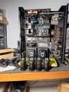
The unit is in a rough shape. Frame and exterior are all rusted and looks like there were some attempts to refurbish with spraypaint. I can't really judge since I myself dont know how to do cosmetics. just ask my Dual 1229 and Sansui AU-D707F ahaha :rflmao:
So this will be just the electrical parts only not really look, though i will be cleaning the unit up while im there which improved how it looks on the inside.

whatsapp-image-2026-09-13-at-4-52-14-pm-2-jpeg.3835665


WhatsApp Image 2026-09-13 at 4.52.14 PM (1).jpegWhatsApp Image 2026-09-13 at 4.52.14 PM (4).jpeg

Aside from the restoration the owner said the phono was losing one channel and i confirmed it
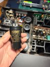
He actually found me from my sales listing for a set of 4 Kemet reservoir caps. I was selling this because i bought the wrong voltage for my AU-D707F. He's requesting to install these too, and specifically requested all power rails be filtered with Panasonic FM. However some values aren't available on Element14 (or Farnell in USA) so I'm informed him we'll be opting for the updated FR lineup and use FM if that's not available.
WhatsApp Image 2026-09-13 at 4.52.14 PM.jpeg

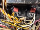
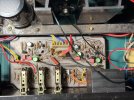
Phono stage seem to have some signs of repair, some input transistors had been replaced with generic transistors. Odd positions (TR01, 03, 05) had 2SA970 BL but even positions (TR02, 04, 06) had 2SA1015. However the fault was found to be the orange input capacitors. i wanted to repair faults before making shotgun changes for the restoration so these were replaced with Nichicon MUSE 10uf. These are supposed to be 4.7uF but i didn't have the correct values yet.

WhatsApp Image 2026-09-13 at 4.52.15 PM (1).jpeg
WhatsApp Image 2026-09-13 at 4.52.36 PM (2).jpeg
WhatsApp Image 2026-09-13 at 4.52.36 PM (1).jpeg
WhatsApp Image 2026-09-13 at 4.52.36 PM.jpeg

And success! Phono is now working both channels. Now we can proceed with the restoration.
Also eagle eyed among you will notice the C05 is reversed, luckily its just in the audio circuit so there's no danger.
 

Attachments

  • WhatsApp Image 2026-09-13 at 4.52.14 PM (2).jpeg
    WhatsApp Image 2026-09-13 at 4.52.14 PM (2).jpeg
    160 KB · Views: 229
  • WhatsApp Image 2026-09-13 at 4.52.14 PM (3).jpeg
    WhatsApp Image 2026-09-13 at 4.52.14 PM (3).jpeg
    118.3 KB · Views: 10
Register to hide this ad
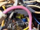
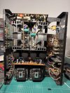
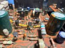
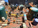
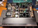
Initial inspection reveals some concerning findings. This is an old unit (as they are since its the 517) and it probably had multiple owners and technicians working on them.
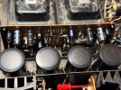
There were plenty of signs of repairs on it, and I probably can trace at least one major fault it had. One reservoir cap has been replaced. tracing through the unit the power supply board had been fully recapped at some point but most of the caps were bipolars (?) and I'm also not sure whether they're originals or counterfeits. Protection relay clips has witness marks for cleaning, I assume, and they measured good so I left it in.
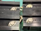
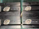
Driver boards were also worked on and 3/4 of the output transistors had been replaced.

So maybe this unit had a catastrophic reservoir failure that took out several components and all the way to the power transistor. One of the fuses also had burn mark but wasn't open.

WhatsApp Image 2026-09-13 at 5.14.54 PM.jpeg
WhatsApp Image 2026-09-13 at 5.14.54 PM (4).jpeg
WhatsApp Image 2026-09-13 at 5.14.54 PM (3).jpeg
WhatsApp Image 2026-09-13 at 5.14.54 PM (2).jpeg
WhatsApp Image 2026-09-13 at 5.14.54 PM (1).jpeg

I'm very familiar with the green Nichicons on the driver board, I'm pretty sure they are fakes as i've seen plenty of them before with different top vent cuts
 
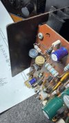
I started work on the power supply & protection board and the reservoir capacitors. All caps were replaced with Panasonic FR or FM. You can also see flanking left n right of the board are the power rails to the phono and other sections, there were also mixture of bipolar and polar capacitors for the +- rails :no:. Dual diodes were replaced with dual 1N4148. There were also one or two lifted traces so I repaired those with PCB copper rivets since the boards are installed vertical and i don't want to rely on the track adhesive to hold the parts.

Previous repair work had also cleaned up the glue residues so that cut my work in half.

WhatsApp Image 2026-09-13 at 5.30.18 PM.jpeg
WhatsApp Image 2026-09-13 at 5.30.18 PM (2).jpeg

WhatsApp Image 2026-09-13 at 5.30.18 PM (1).jpegWhatsApp Image 2026-09-13 at 5.30.18 PM (4).jpegWhatsApp Image 2026-09-13 at 5.30.18 PM (5).jpeg
WhatsApp Image 2026-09-13 at 5.30.18 PM (3).jpeg
WhatsApp Image 2026-09-13 at 5.30.18 PM (6).jpeg

Board is then cleaned before installation. We have fresh wires for the +-51V because the insulation had melted at the capacitor connection points.
When i was checking the fuse, the caps were loose for some reason (?) and they pulled off, so temporarily I jumped one temporarily since i don't have the right specs.
Unit powered up on dim bulb no problem and all voltages read correct. Next we will move on to the phono board.
 
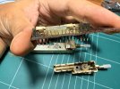
Now moving forward with the phono board we can finally address the issue of mismatched transistors.
Btw i removed the ribbon cables manually with a solder sucker since i dont have a desoldering tool. That was very fun.

The board is quite dirty from just age and uncleaned flux. I first took out the switch for complete cleaning (also manually). Contacts are cleaned with fiberglass brush until they are shiny. I lubed the moving parts with a very light synthetic grease I use for restoring cassette decks.

WhatsApp Image 2026-09-13 at 5.48.50 PM.jpeg
WhatsApp Image 2026-09-13 at 5.48.51 PM.jpeg
WhatsApp Image 2026-09-13 at 5.48.51 PM (1).jpeg
WhatsApp Image 2026-09-13 at 5.48.51 PM (2).jpeg

For the transistors I used A992/C1845. Using the transistor matching circuit I could get the A992 to match down to 0.09mV or less depending on the temperature. After replacing all electrolytics with usual Panasonic I also replaced some film caps in the signal path with Wima. Now that they've discontinued some film caps i don't know what i could use in the future. Anyone has suggestions?

WhatsApp Image 2026-09-13 at 5.48.51 PM (4).jpeg
WhatsApp Image 2026-09-13 at 5.48.51 PM (3).jpeg
WhatsApp Image 2026-09-13 at 5.48.51 PM (5).jpeg

I didnt touch the RIAA network capacitors since they're very high stable and tightly specced for the task. I didn't take them out from the circuit either for fear of damaging the polystyrene layers.

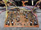
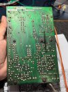
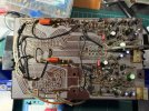
The board (and other boards) is cleaned thoroughly cleaned both foil side and component side. Just a comparison during cleaning of before and after.
WhatsApp Image 2026-09-13 at 6.37.11 PM.jpeg

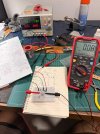
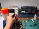
The board is tested on the bench PSU and checked the output response. I have no signal gen/AWG so i'm using a square wave generator on my phone into a DIY inverse RIAA circuit. The frequency response is less than ideal but i still can see sine or square wave kinda. the board tested good but noisy since its outside of the case.
After installation the test is repeated and it seems all is good on the phono.
WhatsApp Image 2026-09-13 at 5.48.51 PM (6).jpeg
WhatsApp Image 2026-09-13 at 5.48.51 PM (7).jpeg
 
Next is the tone control board. I know some people don't really use the tone controls but since this is a comprehensive restoration i'll be going through it as well.
Unfortunately i didn't take photos of the before and after. Treatment is the same with the others. I also switched out the dual diodes with 1N4148 as preventative measure.

Two coupling caps were placed foil side since the mounting was too wide. I also took out the switches for cleaning and contacts were cleaned with fiber brush while moving parts greased. Since we took out the whole assembly I cleaned and lubed the tape monitor switches too. The metal plates had rusted so the action wasn't smooth but now they click quite nice. It mustve been the contact cleaners washing out any lube they had.

WhatsApp Image 2026-09-13 at 6.56.27 PM.jpeg
WhatsApp Image 2026-09-13 at 6.56.27 PM (1).jpeg
WhatsApp Image 2026-09-13 at 6.56.27 PM (2).jpeg

Board looks pretty nice after cleaning. other semiconductors didn't have any prior service signs so i left them in.
I recently got a pair of Yamaha NS1000M and they sound very good. I find myself using tone controls a lot since they're bass light at home. this refurb really makes the tone control more transparent. There's no crackle or pop or anything when the switches are engaged.
 

Attachments

  • WhatsApp Image 2026-09-13 at 6.56.27 PM (3).jpeg
    WhatsApp Image 2026-09-13 at 6.56.27 PM (3).jpeg
    154 KB · Views: 5
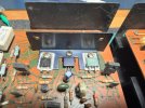
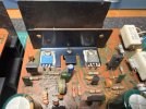
The driver boards had perhaps the most mismatches. input, driver, and power transistors were mismatched.
One board had a 2SD525 in TR12 working against an original 2SB537 output device. not a driver part, and not the complement to the 2SB537

WhatsApp Image 2026-09-13 at 7.12.13 PM (1).jpegWhatsApp Image 2026-09-13 at 7.12.13 PM (2).jpegWhatsApp Image 2026-09-13 at 7.12.13 PM.jpeg

Small signal transistors were mismatched between boards so these will also receive A992/C1845
WhatsApp Image 2026-09-13 at 7.24.13 PM (1).jpeg
WhatsApp Image 2026-09-13 at 7.24.13 PM.jpeg

We can also see the power transistors on one channel is the proper replacement Motorola part MJ15023/22 but the other unit had the original 2SA745A but the complementary part was a Mospec MJ15003.
WhatsApp Image 2026-09-13 at 7.24.13 PM (2).jpeg
 

Attachments

  • WhatsApp Image 2026-09-13 at 7.12.13 PM (5).jpeg
    WhatsApp Image 2026-09-13 at 7.12.13 PM (5).jpeg
    115.9 KB · Views: 2
  • WhatsApp Image 2026-09-13 at 7.12.13 PM (4).jpeg
    WhatsApp Image 2026-09-13 at 7.12.13 PM (4).jpeg
    154.1 KB · Views: 0
  • WhatsApp Image 2026-09-13 at 7.12.13 PM (3).jpeg
    WhatsApp Image 2026-09-13 at 7.12.13 PM (3).jpeg
    141.7 KB · Views: 1
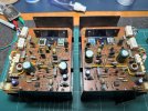
These driver boards are still under construction so I will be updating the board later.
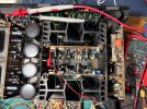
inputs were done again with A992/C1845. Trimmers are replaced with cermets but they're single turn since I couldn't source multiturn ones for the right values plus theyre side adjustment.
Drivers are not replaced yet because i'm still waiting for MJE15030/31 (thought i still got stock but I ran out). Luckily input FETs were good. all of the semiconductors had solder marks, i assume previous tech had gone through them during troubleshooting and repair.
All caps are also Panasonic FR/FM.
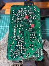
The bottom board actually had the TR3 and TR4 (A992) reversed so I had no bias the first time i fired it up. Good thing it was very easy to find. I thought there was an open resistor somewhere. After cleaning the boards they come out rather smart.

WhatsApp Image 2026-09-13 at 7.28.28 PM.jpeg

For the outputs I chose MJ15003/04. Maybe u guys can advise me better for this choice. I got Multicomp transistors, will there be measurable difference if i get Onsemi? I appreciate any advice.
Fresh thermal paste and mica insulators for the output transistors.

WhatsApp Image 2026-09-13 at 7.28.28 PM (1).jpeg

Zeroing the DC offset and biasing was easy even with the single turns. Well, bias trimmers were touchy but it didn't take long to get almost 20mV.

WhatsApp Image 2026-09-13 at 7.28.28 PM (2).jpeg

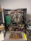
Some more photos of the insides

WhatsApp Image 2026-09-13 at 8.16.01 PM (1).jpegWhatsApp Image 2026-09-13 at 8.16.01 PM (2).jpegWhatsApp Image 2026-09-13 at 8.16.01 PM.jpeg
 
How fast does it come out of protection? If too quick and the DC hasn’t settled down, it will pop. Monitor DC at the speaker terminals when powering it up.

If too quick, changing a cap or resistor value in the RC circuit can slow it down.

Rob
 
As Rob says, but you'll need to monitor the DC offset at the driver board output - before the speaker relay contacts. (speaker terminals are disconnected until the relay closes). ;)

it had been cleaned before. maybe i should replace it anyway?
It depends how it was cleaned, if any kind of abrasive was used the relay is toast. ;)
 
Last edited:
As Rob says, but you'll need to monitor the DC offset at the driver board output - before the speaker relay contacts. (speaker terminals are disconnected until the relay closes). ;)
Ah, yes, normally if it’s not coming out of protection.

I assume since there is a pop when the relay engages that there will be DC at the speaker terminals that will slowly drop.

Also, this is only if the amp is coming out of protection in the first couple of seconds.

I have done it this way on a few receivers that came out protection to quickly. Changing the RC time helped.

Rob
 
Its really less of a pop and more of a tick or low volume click.
The relay engages in probably after 5 seconds or so, plus minus 1-2 seconds. I've zeroed the offset only once after the servicing and now after a week of cooking in the living room playing records and the tv maybe I need to check the biasing and offset again.

It depends how it was cleaned, if any kind of abrasive was used the relay is toast. ;)
Great! Just ordered the Omron part.
 
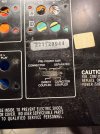
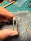
Does anyone know the modern replacement part number for the pre/power separate switch at the back of the 517? Years of contact cleaner had rusted the housing out and one screw seized in it.
 

Attachments

  • IMG_1407.jpeg
    IMG_1407.jpeg
    248.4 KB · Views: 13
  • IMG_1408.jpeg
    IMG_1408.jpeg
    289.6 KB · Views: 11
  • IMG_1409.jpeg
    IMG_1409.jpeg
    284.5 KB · Views: 9
  • IMG_1410.jpeg
    IMG_1410.jpeg
    290.9 KB · Views: 10
I think someone did find a new identical switch, but I am not 100% sure (here on AK), this was quite a while ago so may no longer be available. :dunno:

Update:
How about this

https://www.digikey.co.uk/en/products/detail/1825289-9/450-1576-ND/1202319

(found in a thread here on AK where someone was looking for a replacement or possible 'different approach' to using the stock switch, and added a link to a replacement switch). One drawback is no screw fixing holes in the above replacement.

I searched using AK's search and entering the text "Connected separated"

@penmarker
 
Last edited:
Thanks! I found some replacements from a local brick n mortar store so i cant post the part number. I also had the same issue - the switches either has the correct pin sizes but have no screw mounts, or they have screw mounts but the pins are wider (for bare wire p2p soldering)
 
Back
Top Bottom