• The move to the new server is done. There are some software and database maintenance updates in process. This has us passing the hat around to help out. We appreciate any donations. Seriously, even a dollar helps. The payment page may be found here - https://www.audiokarma.org/support.html

Phase Linear 700-II repair advice needed

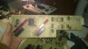
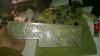
DRS 900 display board..??

This board and the outputs........guy said he was an engineer for PL then Carver, they have been on that shelf for well over 5 years.
Dan
 

Attachments

  • WP_20140628_004.jpg
    WP_20140628_004.jpg
    52.6 KB · Views: 85
  • WP_20140628_003.jpg
    WP_20140628_003.jpg
    55.3 KB · Views: 69
I still haven't talked with him about what he wants to do. Been busy over the weekend. Maybe tonight I'll put together a parts list and price out what it will cost to retrofit the whole thing to more stable outputs. With the way he beats on equipment, it will probably need them at some point.

The new transistors drop in with no mods right? Just set the bias, confirm the current sharing, and life is good ?

Will do on the switch bridge and the cap too. Thanks for confirming what I suspected about that. I don't know why companies do that, but its not the first time I've seen 2 pole switches that didn't use both sides. Often you find that same gear with one burned out pole on the switch because its overloaded, and one thats never been used.
 
Current sharing test comes out OK. Best to worst transistor is about 15% difference, but I can shuffle some stuff channel to channel to even that out better if I wanted to. With a little shuffling magic, I can make both channels be within 10% best to worst. That was only at about 75w of power though, not full bore like the book says. I blew a rail fuse when it hit about 40v of output. I did the test at 20v across 5.5 ohms, since thats what my dummy load comes in at. No more spare fuses, and they aren't the correct size anyhow. That will be corrected when it gets rebuilt. I'll change the small caps too. Plan is to return this in better condition than he bought it in if I'm allowed to.

I left my friend a message suggesting the new output transistors, so we'll see what he does. Given what a single obsolete one costs vs a whole bank of new, it seems like a bad value to replace obsolete parts with more obsolete parts. $20 for a single Delco part vs about $80 for all brand new output transistors.


Unrelated, but I was looking at some of the performance tests in the service manual. It actually says to dead short the output at full power for 2-4 seconds and verify it comes back without problems. I don't think I will be doing that test. It seems like a bad idea. Hell, thats why I'm fixing it now.
 
If the amp's protection circuit is working right it's not supposed to hurt it. The test on a non Series II says bring it up to 1 watt with outputs shorted while monitoring with a scope, verify that everything turns back to normal when the short is removed....
 
Unrelated, but I was looking at some of the performance tests in the service manual. It actually says to dead short the output at full power for 2-4 seconds and verify it comes back without problems. I don't think I will be doing that test. It seems like a bad idea. Hell, thats why I'm fixing it now.

Something else then worth of reading...
 

Attachments

So back to this again. I got the new On-Semi MJ 21196 outputs installed. Unfortunately thanks to a slip of the test probe, I have blown the original RCA 410 driver. Whats a good sub for that? Is there any chance I can use one of the original XPL909 output transistors as the driver? I have 19 good ones here. No problem changing all 4 out if the XPL909 is a good sub. It has one ECG driver in there currently now that I'm sitting here looking at it.


Also, regarding the bias setting. The service manual says 0.20 to 0.60 volts across the resistor. Should I aim for one end or the other of that range, or just peg it for the middle?

Thanks for the help with this beast so far. It would have turned into a boat anchor without you guy's input. Its surely heavy enough to be used for one :)
 
So I think I answered my own question. I found an old thread

http://www.audiokarma.org/forums/archive/index.php/t-148097.html

(last post) that says one of the officially blessed output transistors can be used as a driver. Using a bit of logic and a leap of faith, I figure that means any of the original outputs should be usable as a driver. As such, I stuffed in a pair of XLP909's and its back to operating.

Now on to the problem I was trying to fix when I blew the driver. This thing oscillates at about 1.1 mhz. I have added a 250pf cap from B to C on the two pre-driver transistors per the service bulletin. That brought it down from about 5 mhz. Can I or should I continue to increase the capacitance until it quits acting like a radio transmitter, or is there something else I should be looking at here? The pair of 10 ohm resistors that make up the output filter circuit come in at 6 ohms for the pair in parallel. Is that enough to screw things up? If it is, am I stuck with carbon comp resistors for that spot, or will carbon film do OK ? CF are easy to get, CC not so much.
 
I have now removed all of the output transistors and the drivers. The only thing on that channel is the PL36 driver board. I even tried removing the dummy load and the voltmeter, connecting output direct to the scope with a BNC to alligator clip cable. Still oscillates with a sawtooth waveform at 1.3 mhz, and there is a higher frequency oscillation riding that sawtooth.

I am using mica insulators and thermal grease. The originals were the rubber, and it mentions problems with HF oscillation linked to the rubber insulators.


Some closer inspection reveals the MM4003 pre-driver is actually an NTE part. Maybe a clue ?
 
The resistors in the output network may be wire wounds. Is there a parting line on the case? Most CCs don't have this parting line. Is the first color band wider than the rest of the bands? Those details point to wire wounds. Check out IRC/ TT Electronics brand, SPH series data sheet @ Mouser. Also the output emitter resistors should be the same, different value though. The clue that made me suspicious is the fact that I can never find a CC of less than 1 Ohm, PL emitter resistors are less than 1 Ohm.

Craig

I have experienced the rubber insulators causing problems in PLs, mica and thermal compound is the way to go.

2N3440 and 2N5415/6 usually work in the TO39 positions. MM4003 and 40327 are tough to find.
 
Last edited:
No visible parting line, and all 4 bands are the same width. I've also never seen a wirewound drift upward in value, but that is sort of a common trait with CC. These are the 10 ohm resistors on the output jack, not the emitter resistors. Its a pair of 10 ohm in parallel, tied to a 0.1uf film cap that goes from speaker + to speaker -.

The 0.33 emitter resistors do have the parting line and wider first band. They measure OK as far as I can determine. My ohm meter only has 2/10 ohm resolution but all 20 test the same as far as I can see.

I looked in there closer, and the stock channel had an original MM4003. I now have an original MM4003 and a 40327 in the channel with the new outputs. It still oscillates. I tried caps to ground on the terminal strip where the emitter resistors tie. I got some massive amount of broadband hash before the fuse blew. The unmodified channel has those caps, but it apparently does not work well on the channel with new output transistors.

Whats the TO39 position ? You mean the pre-drivers ?
 
OK so the output network contains CCs and the emitter resistors are wire wounds, I was pretty sure about the emitter resistors. Anyway it's some resistor info I scrounged up working on an Audio Research amp a couple of weeks ago. The last PL I worked was a 400 and I converted it to full complimentary output stage and used the same transistor for drivers and outputs, MJ15024/25s IIRC.

TO39 is the case style of the MM4003 and 40327 transistors. I've seen TO126 style transistors used in those positions as well, MJExxx. Pre-drivers and VAS positions.

The only oscillation problems I've run across in the PLs was the silicone transistor insulators.

Craig
 
Ah, the case style, ok. I don't live in sand-land very often so I'm not terrifically familiar with the case designations. I'm much more a tube guy, but it seems I've been cursed with piles of broken solid state gear at the moment.
 
Tubes are definitely easier to troubleshoot, "usually" much simpler circuitry and tubes don't puke instantly like transistors. Most of the common audio tubes are still in production, though not the same quality, whereas last week's transistor is already obsolete. Then the search for suitable subs begins, sometimes you find something that drops in sometimes you don't. This is where experience comes in, knowing what works and what doesn't. This is also where the internet and all of these forums come in, it's a huge time and money saver to use other peoples' experience and knowledge. It seems like I'm on them constantly throughout the day.

Craig
 
6 ohms is good in that position. What about the caps?? An oscillating amp will eat the Zoebels up....try some .33uf caps accross where you see the 4uf caps in a series 1 schematic on the back wall. That will be 4 caps tota , 2 for each channel.

Th 909's could be causing the oscillation too. Did you change anything on the driver board other than the small cap??
 
OK, so to tie all this up, I got it sorted. At the start of this, I had triangle waveforms and oscillation in the 1 mhz range after replacing the output devices on the left channel. Until that point, I had done nothing with the right channel. I went ahead and converted the right channel and it was absolutely perfect with no special effort taken. That gave me a nice place to work from in terms of diagnostics.

I replaced the Zoebel network with new 10 ohm 3w metal film caps and 0.1uf 630v film caps, no change. Swapped the ECG pre-drivers with the originals from the other channel, no change. Swapped the ECG input amp with a genuine from the other channel and the oscillation went away but the triangles remained. Swapped the PL909's back in as drivers, still no oscillation, still the triangles. The triangle waves were chased to an open 22 ohm resistor on the board (R102, I think it has something to do with the protection circuit) and the two 7.5k resistors were just grossly off-value. I went through and checked the rest of the resistors and everything is on value now. I had previously found some other off value parts, but I guess I missed testing those particular ones.

So back to that input amp. I put it in the other channel, and it works fine there. I can't explain why it works on one channel but not the other, but maybe it was related to the protection circuit issue that I fixed after I found the oscillation problem. Either way, I now have both channels with PL909 drivers, one is internally all ECG parts on the board, the other is all original. Both perform the same as far as input sensitivity and power output. Balance test comes out OK, and I get + and - 1mv DC at the speaker terminals depending which channel I check.

I also have the 4000 preamp sitting here. It was full of broken solder joints and bad connections. Got all that sorted and its working OK now.


Anyway, thanks a million to everyone who gave me info on this beast. It wouldn't be sitting here playing if not for the fine folks here at AK.
 
heh, yeah I found that out.

Vaguely related, but does anyone have a suggested source for replacement input RCA jacks? I just tried to plug in a turntable to test this, and one of the jacks fell apart. Looks like the stock jacks are a shorting design. No clue if they are anything approaching a standard unit or if its pure unobtanium 1970s stuff.
 
Back
Top Bottom