• The move to the new server is done. There are some software and database maintenance updates in process. This has us passing the hat around to help out. We appreciate any donations. Seriously, even a dollar helps. The payment page may be found here - https://www.audiokarma.org/support.html

Philips 594 blows speaker fuses, fine with headphones

Gertjan90

Member
Hi guys,

A friend of mine recently brought me this integrated amp. It was about to be thrown out by the owner of a local bar, because both channels cut out one after the other.

So I took it upon myself to try and safe this nicotine brown workhorse.

Initial testing with headphones revealed that the right channel was weak and left was dead.
After replacing the transistors in the tone board and some elco caps, sound has been restored, but only when using headphones.

When I try to use the speakers, the fuses blew immediately. I checked the speaker connections, but nothing was wrong.
Even without any speakers connected (they use DIN two prong plugs btw), the fuses still blow.

Now, my question is:
Where should I start looking for the culprit?
Sound is fine, with watt meters working and everything on headphones.

Are there any common defects that can cause these problems?
The fuses blow on both channels simultaniously.

All help is appreciated.

PS: I'm very impressed by the build quality and clear lay-out of this entry level amp.
 
Register to hide this ad
Will try and find the sm.
Suggest measuring the resistance between the left speaker posts (red and black). then repeat for right channel. Amp powered off unplugged. It's a long
shot.
 
SM suggests headphones comes off preamp stage.
Also inserting the headphones MAY mute the power amp, the sm is in dutch.

Probably power amp is at fault, outputs/drivers and emitter resisters are suspect.
Suggest diode test outputs and drivers
 
If it's the Philips AH594, then the SM is available free on the hifiengine website (it's free to join, and 'clean') - https://www.hifiengine.com/manual_library/philips/ah594.shtml

As mbz says, the power amp stages are effectively after the headphone connections - and they seem to be disconnected by the insertion of a headphone connector - hence the reason it can work on headphones, but not with speakers. The 2 fuses are in the +59V supplies, only used in the main power amps, 1X left channel + 1X right channel, and they are physically mounted on the same pcb as a lot of the power supply circuitry.

I find it a little odd that both fuses blow - that suggests you have faults in both power amps, left and right, (probably shorted outputs / drivers / etc.). It's certainly possible, but either way, I'd be looking at checking both power amps completely, and probably that whole pcb. I'm not sure what's meant by 'Safety Resistor' in the manual, but I'd add those to the checks as well - they may just be flameproof resistors, but could also be fusible.

From your username & location, I doubt that the Dutch service manual is a problem, but if it is either Google translate can handle it, or I speak Dutch as well...

Alan
 
Hi guys, thanks for the responses.

I previously ruled out the output transistors because I did get sound trough headphones, but now it seems they still might be at fault.
Diode test showed a reading between emitter and collector, so I guess they're toast?

I already tested the driver transistors out of circuit and they're OK.
The safety resistors are just bulky 2W resistors. They're fine, but one of them seemed to have been rather hot at one point, so I replaced the lot.
No change though.

And yes, the SM is in my native language, wich is quite nice.
Quick question, how can I tell which resistors are the emitter resistors and what do they do?
I might check them as well, while I'm at it.
 
I just tested the end transistors out of circuit.
Lefts are dead, as suspected, but on the right they passed the diode test.
Maybe a silly question, but I put in some fuses with the outputs removed (open), and that stopped it from blowing the fuses.
Could this rule out any more shorts or was this test useless?
 
Something still sounds wrong on the right - if the outputs are still good, what was blowing the fuse on the right channel.... As Pete said, it's worth digging back a bit further.
 
strange blowing both sides ..unless someone has been in there before and shorted an outputs collector to heat sink .
 
I did swich the outputs left to right when I started testing.. that might have shorted something on the right side.
But now you mention the short to heatsink; I did notice one of the mica insulators was missing a corner, so I patched it up for testing. Might still have shorted.
I haven't checked the righthand side drivers, but I'll replace all the transistors on the power board, as I'll be ordering up some new outputs anyway.
Will check/replace resistors as I go along.

My go-to store has the MJ15024 and MJ15025, will they be a suitable replacement for the BD313 and 314 ouputs?
 
I don't know the MJ15024 / MJ15025, but I had a look around on the net - the usual replacements for BD313 & 314 in Philips units seem to be MJ15003 & MJ15004 (from a couple of Dutch web site references) - they're certainly still available from the likes of Mouser etc.

If you're ordering outputs etc., I would add some new bias trimmers as well - you'll need to reset the bias with new outputs, and it's not worth trying to clean / use the originals.
 
Last edited:
Quick update:
I've received my new parts and I'm in the process of putting them in.
Soon, I'll be setting the bias, but I've never done this before.

The manual says to measure the current between the R/L fuse and 3455/3456 respectively.
Will I need to unsolder one leg of 3455/3456 to measure the current or could I just measure it over the fuse holder, without a fuse?

Also, which position for the trimpot should I start out in? Max resistance between 6403 and 3423 or max between 6403 and 3429? (for the right hand side)

Thanks in advance!
 
If you have an Ammeter, you should connect it in place of the fuse. Fuse removed, both meter probes on the fuse holder. The Ammeter must be in series with the circuit, it will read the current flowing. You will lose the fuse protection doing this. Or , keep the fuse anf desolder the resistor or some jumper you could find for this purpose.

I usually set the trimpots to the center, read the expected value in the manual, and do a brief test (one second) with a DBT. I expect the reading to be lower (1/2 or 2/3) than the full voltage reading. If too high, I turn off and move the trimpots. When the DBT gives me a low value, I do a brief test at full power, and again, if too far from the specs, power off quickly and adjust the trimpots. Once in the ballpark I let it ON and fine tune while warming up the amp.

If you use a DMM in Amp Mode, and you use the same meter to measure voltages later, I suggest you to SET THE METER TO OHM INMEDIATELY AFTER YOU FINISHED TO MEASURE AMPERES.

The Ammeter is a short circuit for the circuit. If you forget the meter is in Amp Mode and you try to measure a voltage, you'll burn something for sure.
 
Last edited:
If you use a DMM in Amp Mode, and you use the same meter to measure voltages later, I suggest you to SET THE METER TO OHM INMEDIATELY AFTER YOU FINISHED TO MEASURE AMPERES.

The Ammeter is a short circuit for the circuit. If you forget the meter is in Amp Mode and you try to measure a voltage, you'll burn something for sure.

I'd agree with Elnaldo's adjustment approach - and would just emphasize his warnings in the last 2 paragraphs !

The manual says to measure the current between the R/L fuse and 3455/3456 respectively.
Will I need to unsolder one leg of 3455/3456 to measure the current or could I just measure it over the fuse holder, without a fuse?

Just one important point - the Philips manual / schematic is somewhat deceptive in the way it's drawn: the indicated 75mA idle current is the TOTAL idle current being supplied to each main amp stage. It is not all passing via the 3455 or 3456 resistors (most of it goes directly to the respective drivers & outputs) so it cannot be measured by lifting one leg of the 3455 or 3456 resistor and measuring there. The fuse holder is the correct location to measure it, without the fuse obviously.
 
I'd agree with Elnaldo's adjustment approach - and would just emphasize his warnings in the last 2 paragraphs !


Just one important point - the Philips manual / schematic is somewhat deceptive in the way it's drawn: the indicated 75mA idle current is the TOTAL idle current being supplied to each main amp stage. It is not all passing via the 3455 or 3456 resistors (most of it goes directly to the respective drivers & outputs) so it cannot be measured by lifting one leg of the 3455 or 3456 resistor and measuring there. The fuse holder is the correct location to measure it, without the fuse obviously.

Can you post a link to the procedure? I'm reading the hifi engine service manual, but didn't find the instructions.

Anyway, being familiar with philips schematics, (I own a Philips amp), I know the bias adj.instructions are not clear. In my unit, you are instructed to desolder a solder bridge in one PCB trace, insert an ammeter, unmount one transistor from the heatsink, and disconnect the power supply to the other channel.

Being all that absolutely confusing, I finally just measured the voltage drop across the emitter resistors, what I'd do in this unit too.

What I'd do: measure VOLTAGE from emitter to emitter, (across both 0.24 ohm resistors, R3449-3451), and adjust both channels to read 10mV on the meter, what means 20.8mA idle current, a conservative and safe value, and check the current at that mentioned fuse or the voltage across R3455/3456 and calculate the actual current flow through the amp section, and check with the values in the manual. If too far (specially if you read too high current), perhaps you need to lower those 20.8mA but I think it's a low value, it won't damage the amp.

You can measure at one 0.24ohm resistor and adjust to 5mV, but measuring just 5mV is less accurate.

If you follow my instructions about adjusting with a DBT , I'd adjust to have 5mV with the DBT, and then check at full power and adjust to 10mV (from emitter to emitter, across two 0.24 Ohm resistors)
 
Can you post a link to the procedure? I'm reading the hifi engine service manual, but didn't find the instructions.

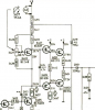
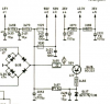
I'm just using the same hifiengine service manual schematic - I couldn't find any 'instructions' in the manual either - but, the 75mA is clearly indicated for each channel, with adjustment via the bias trimmers. It can only be the total current via the 3 positions marked "+2" (or "+3" for the other channel) - as it's impossible to pass 75mA via the indicated 3455 (or 3456) resistor only, without burning it out.... they're both shown as only 0.25W resistors.

Capture1.PNG Capture2.PNG
 
Back
Top Bottom