sae-7125
Super Member
instead of photo-bombing an older thread, like the one listed below, i decided to start another new thread.
some youtube vids were informative but lacking in regards to intricate repair not to mention "part 5" of one persons vid ended in loathing contempt for this particular table and its unilateral idiosyncracies i.e. repair tech snarling at something with an undesirable learning curve (we all have been down that route more than a few times).
in regards to the lift/drop cue button repair or simply realigning the easy to disrupt metal lever in the sub-assembly. no weird mods or adding design "enhancements" was necessary, much to my surprise.
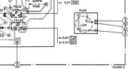
i will try to describe my findings with a series of photos since typing a book is too much work. the 312 being repaired, initially had a transistor go into retirement without the approval of the rest of the circuit. and so damage control was needed after the party died down. the main board was rebuilt, sorry no photos of pcb top side were take, and then the true headache started, cue switch be thy name. for those who have issues with the capacitive touch speed/off button sensitivity and it not latching with a brief touch there is a pot to adjust the sensitivity, works great.

a few basics first, brand, and yes the original power button still functions like it should.

model, even though the area lighting is too bright for the LED indicators. cue button in normal "up" position (after mech adjustment was successful)
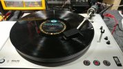
some vinyl in not so great condition.

the particular sonic flavor being spun for a few rev's.

interior birth certificate, not that such things help to diagnose an issue. case screws are m4 15mm, if its not listed in the service manual.

pardon the mess, its the norm for this hobby.

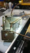
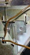
mech removed and easily shows how badly that the control lever is out of place, a simple alignment nudge takes care of the issue.
i will finish posting the switch mech closeups in the next post once the photo storyboard is ready. lots of photos to process right now.
Problem with cueing mechanism on my GA-312
I have always liked the design of Philips GA-212/312 series. A Philips GA-212 was my first serious TT back in 1973. I find that I now have a problem with the switch that controls the cueing mechanism on my GA-312. The switch does lower the arm as designed, but arm immediately lifts back up as...
audiokarma.org
some youtube vids were informative but lacking in regards to intricate repair not to mention "part 5" of one persons vid ended in loathing contempt for this particular table and its unilateral idiosyncracies i.e. repair tech snarling at something with an undesirable learning curve (we all have been down that route more than a few times).
in regards to the lift/drop cue button repair or simply realigning the easy to disrupt metal lever in the sub-assembly. no weird mods or adding design "enhancements" was necessary, much to my surprise.
i will try to describe my findings with a series of photos since typing a book is too much work. the 312 being repaired, initially had a transistor go into retirement without the approval of the rest of the circuit. and so damage control was needed after the party died down. the main board was rebuilt, sorry no photos of pcb top side were take, and then the true headache started, cue switch be thy name. for those who have issues with the capacitive touch speed/off button sensitivity and it not latching with a brief touch there is a pot to adjust the sensitivity, works great.
a few basics first, brand, and yes the original power button still functions like it should.
model, even though the area lighting is too bright for the LED indicators. cue button in normal "up" position (after mech adjustment was successful)
some vinyl in not so great condition.
the particular sonic flavor being spun for a few rev's.
interior birth certificate, not that such things help to diagnose an issue. case screws are m4 15mm, if its not listed in the service manual.
pardon the mess, its the norm for this hobby.
mech removed and easily shows how badly that the control lever is out of place, a simple alignment nudge takes care of the issue.
i will finish posting the switch mech closeups in the next post once the photo storyboard is ready. lots of photos to process right now.