• The move to the new server is done. There are some software and database maintenance updates in process. This has us passing the hat around to help out. We appreciate any donations. Seriously, even a dollar helps. The payment page may be found here - https://www.audiokarma.org/support.html

Pilot 240 Rebuild

The 100 Ohm resistor is power supply restricting

Archie2,

I didn't get a chance to go into details of my Pilot conversion to a power amp.

Since the amp is Push-Pull it naturally cancels noise. Since it does this you might consider removing the resistor and just tying the two cap sections together that are connected to the rectifier and the output transformers.

You should be pleasantly surprised at just how much more dynamic the amp will be.

Some would say, oh! that's hard on the rectifier! Well the amp uses a 5AR4 slow turn rectifier as it is. The amp above has been running on 3-400uf that I can remember now for 10yrs plus and has had no issues at all in fact all of the tubes are still 100% and if people think that's hard, my own monoblock SET amps pictured in my avatar are running 1800uf @ 500 VDC each and I use no resistors in my supply path just SS diodes to drop noise over so my DCR is nothing but the power transformer which make the amps unbelievably fast and powerful and yeah that's a strain that has cost me 10% of the slow turn on GZ37 rectifiers life over a 5 yr period I do this because I'm interested in pure performance not getting 20-30 yrs out of a rectifier. Hell I'll likely be dead so I want to hear it now! So the couple hundred uf's you have is not really an issue in my experience.

There are other amplifiers that do this such as the legendary EICO HF81 an EL84 Integrated amp as the Pilot.

The EICO will run circles around a stock Pilot 240 IMO. But! with the Pilot's supply set up like the EICO the Pilot pulls ahead as it has very,very good output iron even better than the Pilot console amps that many people have on this forum. My buddy who owns the above amp owns two Pilot console amps and their iron is not in the same league IHO, but the consoles are still nice IHO. I haven't heard the HF81 but I have its schematic, and I don't think the HF81 output iron is quite in the same class as the Pilot 240.

My buddy bought his Pilot for maybe $150 brought it home fired it up and was severely disappointed. It had what is referred to as knob disease meaning the controls were noisy and not tracking well for left-right balance along with selector switch issues not to mention all the switches and lengthy signal paths. I had a schematic and saw a simple and sensitive power amp. I wired it direct in the chassis and called him to listen to it! He was thrilled! though his wife did not like its looks so we made it look good by pulling the iron repainting the iron gloss piano black he got some brass and had a metal shop cut the holes. He made a simple walnut wood skirt and copper bottom plate. I redesigned the layout which made the amp substantially quieter. It was one of my favorite projects that I ever under took. Some say the EL84 is the best of all Pentodes and it wasn't until hearing the amp drive my buddy's $6000 Dunlevy 4's that I understood literally the legend of the EL84 or the Pilot for that matter.

Just my 2 cents worth!

Cheers

SET12
 
Removing the 100 ohm wirewound resistor? How about replacing it with a 50 ohm wirewound? Right now I'm trying to restore it stock. Mods may come later. Thanks for the info.
 
Last edited:
I would go from the rectifier to a 40uf cap then through the 100 ohm 10W power resistor then the following cap should be two 40's combined. That is what my schematic is showing. You could put a 22uf capacitor in parallel with the 40/40 combo under the chassis to make the total 102uf. Which version do you have, the 4 ohm grounded version like I have?


Right now wire goes from the 40 uF can to #8 pin on the rectifier where it connects with the 100 ohm wirewound which connects to the 80uF in the same can. It also connects with the 10k resistor that bridges the 2 cans and connects to the 20uF cap in the 2nd can.
 
Removing the 100 ohm wirewound resistor? How about replacing it with a 50 ohm wirewound? Right now I'm trying to restore it stock. Mods may come later. Thanks for the info.

Archie2, A 50 ohm is just as bad as the 100. Leaving it out doesn't make any difference to the rest of the amplifier. But it really affects the output stage which is the real consumer of energy.

Lets put it to you this way! The 50 ohm's is about the same resistance as the power transformer internally itself.

Another analogy would be like a car pulling a trailer!

Take the trailer away and the car can go considerably faster! :yes:

The way to think about it electrically is energy transfer :D

If resistance is in path, that's what is called a time constant.

Because the cap has to charge over a period of time.

Take away the resistance and the energy is instant. :yes:

This is where dynamic slam comes into play!

Its not about how much power one has but what the individual watt can do!

Try to imagine the 10 watts I have! They are more powerful in their expression then many 1-200 watt solid state amplifiers.

Why you may ask?

Well partially because of the amount of energy that tube amps have.

That energy is measured in Joules and typically many SS receivers or typical SS Japanese mid fi amplifiers are lucky to make 25 Joules or so for 50-100 watts which would be roughly .25 joules/watt for a 100 watts roughly.

Your Pilot for 20 watts with 200 uf's @ 330 VDC makes 10 Joules or roughly .5 joules /watt.

This is roughly how tube amps can keep up with SS to a degree, but there is of course more to this.

My tube amps total have 450 Joules, 225 joules/amplifier or 22.5 joules/watt and with a power supply DC resistance on nearly zero ohms other than the power transformer, you can image the dynamics that can take place!

So go ahead and put the 100 ohm in, it will be that much more dramatic should you care to compare and you can always try this using a jumper wire to bypass the 100 ohm.

When I demonstrated this on a hunch for my buddy Don, I asked him afterward if he wanted the 100 ohm resistor back in? He replied "I'll break your arm if you try!"

All of my power supply design work has been based on this principle.

My Phono preamplifer has a 900 Joule power supply.

As you can see here I don't fool around. And as my friend Don tells me, I don't do anything unless my hair is on fire!

Heres a partial view of the phono supply and I might add its near zero ohms as well!

Phono%20Stage%20Power%20Supply-th.jpg


SET12
 
Last edited:
Archie2, A 50 ohm is just as bad as the 100. Leaving it out doesn't make any difference to the rest of the amplifier. But it really affects the output stage which is the real consumer of energy

Let me see if i am understanding this. You design your p/s without any resistors? Could you post a p/s scheme of an example? Always willing to try new things. Stan
 
Let me see if i am understanding this. You design your p/s without any resistors? Could you post a p/s scheme of an example? Always willing to try new things. Stan

I'd like to see that too.

I work nights guys so I'll try and get back to you in the morning as I could find anything that I could post fast, but I will go into more detail of what I learned from legendary people about this and other phenomena that I discovered in the process of fast powerful supplies.

Stay Tuned :thmbsp:

SET12
 
Looking at those pictures of your amp takes me back. My amp looks completely different underneath now. Judging by all the connections at the back of the amp you have the same model as I do. There are a bunch of ways the speakers can be wired to this amp, its amazing how advanced this amp was for its time. I am keeping my eyes out for pilot schematics pertaining to their extension speakers. They incorporate some sort of limiting circuit that allows you for volume limiting. The next thing I was planning to do with this amp is use it for a Bi-Amp set up using also a GainClone power amplifier to drive some 12" woofers. I need to design a small signal butterworth crossover circuit (Low/High Pass) using LM4562NA chips.
 
Last edited:
I work nights guys so I'll try and get back to you in the morning as I could find anything that I could post fast, but I will go into more detail of what I learned from legendary people about this and other phenomena that I discovered in the process of fast powerful supplies.

Stay Tuned


That would be great!! Thanks, Stan
 
Power Supply a Different Approach

That would be great!! Thanks, Stan

Wow Stan! I can see your enthusiasm for this great hobby of ours :yes:

First off I want to tackle Archie2's Pilot supply down loading these schematics maybe tricky for me so this may take some time hopefully I can get the thumb nails to work so you can see these at a decent size.

Ok the first is the EICO schematic not what I wanted with the (124603) but it works, seems AK doesn't like uploading the same files twice the thumbnail works good but if you right click and click view you'll get a better image and you can enlarge it as well.


View attachment 124603

Ok, so heres what I want you to eye up! Notice the 340 volt source in the supply.

Notice the 340 source is tied directly to center tap on the primary of the output transformers :yes:

So the pair of EZ81 rectifiers feed the output stage directly.

This folks :yes: is how the EICO HF81 gets much of its loved reputation for its dynamics :D

The screens have their own supply which is the 330 volt source.

The Pilot that I did, we tied the screens directly to the the center tap on the primary of the output transformers with a 150 ohm grid stopper to each screen this is of course is pure Pentode mode just like the EICO.

I don't have the Pilot 240 schematic handy but these two schematics show basically what I did with the Pilot 240 circuit.

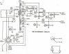
Ok heres the original Pilot supply!

Pilot Power Supply.jpg

Now as you can see the 100 ohm resistor in the supply path. When I first did this I just put a Radio Shack jumper across it to listen to it. I knew the worst that might happen is I might hear an increase in noise. But I had a couple hundred uf's there which was double of the stock supply. And as I said we listened to it and our jaws were on the floor from the dynamics alone :D and of course the :music: was sweet and even more informative. The whole amp was so much more involving like toe tapping instead of slow weakish and to some extent a little boring in contrast to the 100 ohm being in the circuit!:yes:

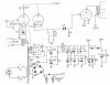
And here is the Pilot circuit I'm using, gain is set for 30db with the 10k on the 16 ohm tap this gives about 5-6db of feedback. The amp has a lot of gain from the EL84's which is more than twice that of typical EL34's.

Basic Pilot Circuit.jpg

This amp may very well sound better than the EICO HF81 especially warmer due to the lower feedback level which is typical of what EL84 Manley amps allow their users the option of.

Ok, Its getting late so I'm going just give a couple of points on the Diode Supply for now and I will get back again tomorrow.

Here's an 811-10 schematic that I think it was Bob a forum member here had drawn up after consulting with me. I'm sure he won't mind.

BobsTube.jpg

Ok you will see a choke and it is pretty big for a 1 Henry. Notice the DC Resistance is just 5.6 ohms

Notice the two Diodes :D These feed each of the two 40 uf Polyprop caps a very high quality cap the rest in front are Electrolytic's which are stacked for a higher working voltage. They have bleeder resistors for voltage stabilization as well as bleed off to drain the supply.

So this supply is very, very fast for energy transfer! Charge and discharge times are very fast!

Notice the Diode on the 6.3 volt supply which the supply has to supply 4 amps for the 811 heater. The main use of the diode between the caps is to drop noise of course and to have as small of a voltage drop as possible.

So what can these diodes do in the high voltage supply? :scratch2:

Well I saw this in an old solid state book that the Engineer said was being used for isolating each of an amplifiers channels. Its what I call a dual mono reserve. :yes: But not a true dual mono supply. But dang close as the diodes the Engineer said isolate the supplies from each other by more than 80db! :thmbsp:

This is because as each supply cap discharges they are blocking each other with their cathodes allowing for fast discharge.

Remember how it is said big supply caps sound bad? and its a :nono:, well not with this :D

I'll be back tomorrow :thmbsp:

Cheers

SET12
 
Last edited:
Power Suppy Design a different approach!

Great info so far. Gonna study it over. Thanks! Stan

Good morning Stan,

Ok, Here's just one possibility with using Diodes for a highly isolated stereo power supply using one rectifier tube and one power transformer and creating what I call a dual mono reserve that highly isolates a left and right channel power supply.


The Diodes themselves of course drop supply noise over themselves and of course while not as effective as resistors or chokes they do offer some additional superior benefits.

PP amplifiers typically can run right off a rectifier tube because they naturally cancel noise. Driver stages maybe another matter but one can use resistors or chokes with this type of circuit as well.

In the driver stages one could make use of a higher DCR choke and not see as much as a loss in speed of the supply simply because the current demands are lower.

But output stages really like the fastest possible speed and this means keeping DCR's to a minimum for maximum dynamic slam.


So how does this particular circuit work?

So a diode allows deep current flow in one direction while blocking current flow in the opposite direction.

The first, is a highly isolated supply allowing for very fast charging and discharging. This is because the internal resistance is seen as nil in one direction and extremely high in the other direction.

As you can see we have a rectifier tube it feeds a cap,then goes to a diode 1 and feeds a second cap then another diode 2 which feeds a third cap.

Now at the third cap we are at a diode junction with two anodes connected to the third cap.

You see the two anodes! This is were left and right channel isolation begins:yes:

As you know DC current flow thru a diode is from the cathode (the straight line connected to the triangle) to the anode (triangle pointed to the line).

Lets say the left channel pair of caps were to suddenly discharge.

While the right channel is fully charged, the left channels diode is going to block current flow from the right channels charged caps allowing the left channel to fully discharge at the fastest possible speed.

Now you see two pairs of caps above and below one another.

These are the left and right channel main supplies for both the output stage and the driver stage. They are every bit as isolated from one another as the left and right channels are.

Each of these caps have the ability to quickly discharge or charge without effecting one another. Not to mention their very fast time constants for punchy dynamics.

Sound Quality

Now for the strange phenomena that I have observed.

In my experience with this, one can use large electrolytics for bulk say the first three caps after the rectifier then for the final four use your favorite premium caps without any signature from the bulk electrolytics and no bypasses needed on the electrolytics.

Typically we know that large value caps in general are not a good idea for sound quality.

But the sound I get from my 10 watt amps with 1800uf's of electrolytics each is that of my AEON caps which are superbly transparent along with tremendous speed and punch transparency with gobs of warmth. There is nothing slow or dark or wimpy about my SET amps.

I have a phono stage diode isolated with 5500ufs of computer grade caps along with 3-40uf AEONS/channel for each triode gain stage in an 11 section pie filter.

Strangely when the pie filter gets that long the sound got to be very ugly but I discovered a trick that gave me the same stunning speed, dynamics and transparency that my amplifiers have.

More on that tomorrow :smoke:

SET12
 
Back
Top Bottom