• The move to the new server is done. There are some software and database maintenance updates in process. This has us passing the hat around to help out. We appreciate any donations. Seriously, even a dollar helps. The payment page may be found here - https://www.audiokarma.org/support.html

Pilot 602 (aka RCA Radiola Mark I)

johntp

New Member
Hello, folks,

This is my first post. Lurked for years to get valuable info about vintage tube amps and vintage turntables.

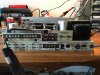
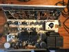
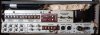
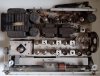
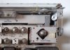
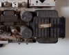
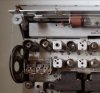
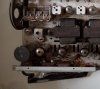
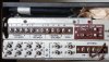
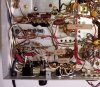
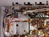
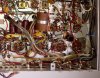
Now I'm starting my first tube amp project and I thought some here might find it interesting. I've attached a couple of pix with more to follow as I dive in.

I've searched the net high and low for info on this receiver and found none. I expect the astute among you will notice the chassis is actually a Pilot 602 of early 60's vintage.

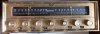
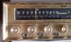
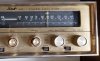
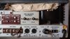
Of course, the big question is why the complete re-work of the front controls. And I mean complete. The original 602 compliment of seven knobs is increased to ten with the addition of an AFC control, a 'Comp'(loudness?) control, and the splitting of the ganged treble and bass controls into individual knobs for each channel. Four of the slide switches and the input selector knob are replaced with a set of eight push buttons. The on/off slide is moved from the bottom left to the center between the channel controls. The tuning scales are moved toward the center and the tuning-eye is replaced with a new eye for each scale mounted at the outer ends.

All this means the old 602 front panel is replaced with a new one which is, as far as I can tell, a nearly production quality, hard chromed aluminum plate with engraved letters on the main control label band and on the bezel. The grid-pattern engraved skin is applied to the face plate with and intentional split between the right channel treble/bass controls. All in all, this is a pretty amazing re-working of the original 602 front end.

My first theory is that this a near production prototype of an RCA product based on the Pilot 602 chassis. I heard from Uncle Mike over at Vintage Asylum that this sort of prototype would show up from time to time in the South Jersey/Philly area since the RCA labs were in Camden, NJ.

If any one other thoughts or info I'd love to hear from you.

And if you've done a Pilot 602 restoration and would share the parts list, I'd be deeply in your debt.

Thanks,

John
 

Attachments

  • pilot602-1frnt.JPG
    pilot602-1frnt.JPG
    103.3 KB · Views: 158
  • pilot602-2back.JPG
    pilot602-2back.JPG
    96.7 KB · Views: 144
  • pilot602-3above.JPG
    pilot602-3above.JPG
    136 KB · Views: 145
Register to hide this ad
Interesting, never seen this before. I wonder if this was the prototype for what eventually became the MX-7

1112072328129.JPG
 
Interesting, never seen this before. I wonder if this was the prototype for what eventually became the MX-7

1112072328129.JPG
Hey, gadget,
You might be on to something. Definitely a front panel resemblance. It looks they sourced a different chassis or made one of their own.

Thx,

H
 
johntp......I have seen that RCA unit or another just like it before...... somewhere online, maybe on the auction site. Could have been a few years ago.

I own a Pilot 602, that was rebuilt by another forum member about 10 years ago. BTW the Pilot still works great.....

There's a detailed thread describing the rebuild here:
http://www.audiokarma.org/forums/index.php?threads/reworking-a-pilot-602.177551/
This is probably the one u saw. I got it off the site about 18 months ago. Seller had no particular provenance info.

I think i’ll reach out to that AK-er for more details.

Thx,

J
 
This is probably the one u saw. I got it off the site about 18 months ago. Seller had no particular provenance info.

I think i’ll reach out to that AK-er for more details.
Thx,
J

If you look at the high res underside photo on page 2 of that thread, you can see the new parts, mostly orange drop caps and diodes.

Have you tested the amp ?

The only thing I don't like about the 602 is that the phono section was designed for a higher output ceramic cartridge, and doesn't work
well with a low output magnetic cartridge. I've mostly used mine for listening to my old cassette tapes on my Akai tape deck.
 

Pilot Model 602SA FM MPX - AM
Stereo Receiver


SPECIFICATION AND FEATURES

All measurements made with both channels operating

AMPLIFIER SECTION

Output (IHFM Music Power): 30 watts
Frequency Response (+- 1 dB): 10 to 40 kc
Harmonic Distortion (IHFM): 1%
Hum: -80 db

INPUT SENSITIVITY

Magnetic Phono (TT)**: 3 mv
Magnetic Phono (RC): 12 mv
Tape Record.: 110 mv
Tape Head: **
Speakers Outputs per channel: 4, 8, 16 ohms
Center Speaker Outputs: yes
Tape Output: yes
Front Panel Headphone Output: ***

CONTROLS

Power: yes
Automatic Shutoff: yes
Speaker Selector: no
Tuning: yes
Separate Brass & Treble: yes
Master Volume: yes
Scratch Filter: yes
Rumble Filter: yes
Phono Input Selector: yes
Loudness: yes
Tape Monitor: yes
FM Muting: no
Mode: yes
Selector: yes

TUNER SECTIONS

FM - Sensitivity ((IHFM): 3 μv
Harmonic Distortion at 100% Modulation: 1%
Frequency Response (+-1db): 20 to 20 kc
Capture Ratio: 4 db
Tuning Indicator: Eye
FM Detector Band Width: 800 kc
FM IF Stages: 3
Automatic FM Stereo Indicator: Yes
Stereo Separation across the entire audio spectrum: Better than 30 db
Antenna: 300 Ohms balanced, 72 Ohms and built-in: Yes
AM - Sensitivity: 3 μv
Harmonic Distortion: 1%
Tuning Indicator: Eye
Antenna: built-in plus connections for outdoor: Yes

DIMENSIONS

High: 5 1/8"
Wide: 14 5/8"
Deep: 14 7/8"
PRICE: with cover $299.50

*
Tape Head can be played back by phono from phono and connecting tape head leads.
** TT inputs can be used for tape head playback.
*** Headphones can be used by connecting to speaker terminal boards.
 
Last edited:

Pilot Model 602SA FM MPX - AM
Stereo Receiver


A PICTURE IS WORTH A THOUSAND WORDS

I'm very impressed with this incredible similarity between RCA Radiola Mark I and the Pilot 602 tube receiver. In my opinion it's a "prototype" made by Pilot, based on a commercial well successfull Pilot 602 to RCA. You are lucky, it's a rare equipment. Two months ago I acquired, here in Brazil, a Pilot 602 in very good condition. For those willing to compare both receivers I've posted here some pics of mine, after all, "a picture is worth a thousand words".

Obs. The manual and the schematic diagram of the original Pilot 602 FM MPX - AM Stereo Receiver can be acquired in the Howard Sams, Photofact Folder 525-11 or in the THE SCHEMATIC MAN.com web site
.

LINKS

Howard Sams - Photofact Folders:
https://www.samswebsite.com/en/photofact/details/index/id/119062


The Schematic Man.com:

https://theschematicman.com/instantdownloads.htm#!/Photofact-Sets-500-550/c/33454019/offset=100

Thanks folks.
 

Attachments

  • Pilot 602 Tube Receiver - Front.jpg
    Pilot 602 Tube Receiver - Front.jpg
    69.5 KB · Views: 47
  • Pilot 602 Tube Receiver - Back.jpg
    Pilot 602 Tube Receiver - Back.jpg
    78.1 KB · Views: 48
  • Pilot 602 Tube Receiver - Above.jpg
    Pilot 602 Tube Receiver - Above.jpg
    112.5 KB · Views: 48
  • Pilot 602 Tube Receiver - Bottom.jpg
    Pilot 602 Tube Receiver - Bottom.jpg
    205.5 KB · Views: 47
Last edited:

Pilot Model 602SA FM MPX - AM
Stereo Receiver


A PICTURE IS WORTH A THOUSAND WORDS
(cont).
 

Attachments

  • Pilot 602 Tube Receiver - Front 1.jpg
    Pilot 602 Tube Receiver - Front 1.jpg
    112.6 KB · Views: 20
  • Pilot 602 Tube Receiver - Front 2.jpg
    Pilot 602 Tube Receiver - Front 2.jpg
    111 KB · Views: 20
  • Pilot 602 Tube Receiver - Above 1.jpg
    Pilot 602 Tube Receiver - Above 1.jpg
    89.2 KB · Views: 19
  • Pilot 602 Tube Receiver - Above 2.jpg
    Pilot 602 Tube Receiver - Above 2.jpg
    93.9 KB · Views: 17
  • Pilot 602 Tube Receiver - Above 3.jpg
    Pilot 602 Tube Receiver - Above 3.jpg
    109.7 KB · Views: 17
  • Pilot 602 Tube Receiver - Above 4.jpg
    Pilot 602 Tube Receiver - Above 4.jpg
    103.6 KB · Views: 18
  • Pilot 602 Tube Receiver - Back 1.jpg
    Pilot 602 Tube Receiver - Back 1.jpg
    119.9 KB · Views: 18
  • Pilot 602 Tube Receiver - Back 2.jpg
    Pilot 602 Tube Receiver - Back 2.jpg
    106.8 KB · Views: 21
Last edited:

Pilot Model 602SA FM MPX - AM
Stereo Receiver


A PICTURE IS WORTH A THOUSAND WORDS
(cont).
 

Attachments

  • Pilot 602 Tube Receiver - Bottom 1.jpg
    Pilot 602 Tube Receiver - Bottom 1.jpg
    195.3 KB · Views: 15
  • Pilot 602 Tube Receiver - Bottom 2.jpg
    Pilot 602 Tube Receiver - Bottom 2.jpg
    168.6 KB · Views: 14
  • Pilot 602 Tube Receiver - Bottom 3.jpg
    Pilot 602 Tube Receiver - Bottom 3.jpg
    194.9 KB · Views: 13
  • Pilot 602 Tube Receiver - Bottom 4.jpg
    Pilot 602 Tube Receiver - Bottom 4.jpg
    179.2 KB · Views: 13
Last edited:

Pilot Model 602SA FM MPX - AM
Stereo Receiver


The Pilot 602 utilizes a set of 17 vacuum tubes:

V1 - ECC85/6AQ8 (FM RF Amp/Osc Mixer)
V2 - 6AU6 (FM IF Amplifier ?)
V3 - 6AU6 (FM IF Amplifier ?)
V4 - 6AU6 (Ratio Detector Driver ?)
V5 - 6BA6 (AM RF Amplifier ?)
V6 - 6BE6 (AM Converter ?)
V7 - 6BA6 (AM IF Amplifier ?)
V8 - EM84/6FG6 (Tuning Indicator)
V9 - 7025/12AX71 (TT & RC Inputs A)
V10 - 7025/12AX7 (TT & RC Inputs B)
V11 - 12AX7/ECC83 (Tone Net. Driver A B)
V12 - 12AX7/ECC83 (Phase Inv./Driver A)
V13 - 12AX7/ECC83 (Phase Inv./Driver B)
V14 - EL84/6BQ5 (Power Output A)
V15 - EL84/6BQ5 (Power Output A)
V16 - EL84/6BQ5 (Power Output B)
V17 - EL84/6BQ5 (Power Output B)

POWER TRANSFORMER

VOLTAGES AC
PRIMARY BLK - 117 Vac (130 WATTS ~ 1,5 Ω)
SECUNDARY RED - 250 + 250 Vac (6,2 + 6,5 Ω)
SECUNDARY GRN - 6,3 Vac (Pilot Lights)
SECUNDARY BRN - 6,3 Vac (Tube Heaters)
SECUNDARY BLU - 6,3 Vac (Tube Heaters)

POWER SUPPLY

VOLTAGES DC

1 SOURCE - 330 Vdc
2 SOURCE - 200 Vdc
3 SOURCE - 150 Vdc
4 SOURCE - 125 Vdc

A SOURCE - 140 Vdc
B SOURCE - 140 Vdc
C SOURCE - 140 Vdc
D SOURCE - 140 Vdc

CAN CAPACITORS (Twist Lock)

CAPACITOR 1 (Two Sections)
SECTION A - 40μF x 400 VDC
SECTION B - 80μF x 400 VDC

CAPACITOR 2 (Three Sections)
SECTION A - 20μF x 350 VDC
SECTION B - 40μF x 350 VDC
SECTION C - 40μF x 350 VDC

CAPACITOR 3 (Three Sections)
SECTION A - 40μF x 300 VDC
SECTION B - 80μF x 250 VDC
SECTION C - 40μF x 250 VDC
 
Last edited:
Julio Cezar,

Thank you for the information and pictures of your 602SA. :thumbsup:

In your listing you indicate:

POWER TRANSFORMER

VOLTAGES AC
PRIMARY BLK - 117 Vac (130 WATTS ~ 1,5 Ω)
SECUNDARY RED - 250 + 250 Vac (6,2 + 6,5 Ω)
SECUNDARY GRN - 6,3 Vac (Pilot Lights)
SECUNDARY BRN - 6,3 Vac (Tube Heaters)
SECUNDARY BLU - 6,3 Vac (Tube Heaters)

In my schematics, I have:

POWER TRANSFORMER

VOLTAGES AC
PRIMARY BLK / RED-BLK - 117 Vac (130 WATTS ~ 1,5 Ω)
SECONDARY RED / RED - 250 + 250 Vac (6,2 + 6,5 Ω)
Secondary RED-WHT - center tap of the high voltage secondary RED / RED This is the 160VDC source.
SEOUNDARY GRN / GRN-YEL - 6,3 Vac (Pilot Lights)
SEOUNDARY BRN / BRN-YEL - 6,3 Vac (Tube Heaters)
SEOUNDARY BLU / BLU-YEL - 6,3 Vac (Tube Heaters)
 
Last edited:
Back
Top Bottom