

You are using an out of date browser. It may not display this or other websites correctly.
You should upgrade or use an alternative browser.
You should upgrade or use an alternative browser.
Pilot SA-260/SP-210 Pwr Supply
- Thread starter ronton3
- Start date
Over a 12 hour period I implemented the 3 phase plan described by Tubeactive to reform the Bell 2440 caps . It worked. This amp has a much more appealing sound than I had anticipated, I thought the rather small output trfs were a bad sign, shows how little I know. It is very quite and sounds great even with original caps, although I believe there is a leak in the fixed caps, which I will probably not be able to resist changing to Russian oils. The 2 filament supply caps were replaced, probably about 20 years ago by me, it has been on the shelf since, who knows why I did not complete the restoration, this is a very well made amp. The only disappointment is loud hum on the phono outputs. If anyone has an idea there I will be happy to hear it. Thanks Tubeactive for the reforming explanation, I will continue to use it in the future.
 First test.
First test.
Excellent ! Good progress ! I am glad the Bell can ring in some tunes. What is the voltage at that can section ? If it is under or over 160V, you can probably fit a 100-200 uf at 160-250VDC instead of that 20u/450V cap. Larger capacitance for the phono stage has many sonic benefits to look forward to....ENJOY !

s-petersen
Scott
One thing to remember, if you go with lower voltage value caps, if the unit is ever run without the downstream tubes, the caps could explode from over voltage
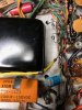
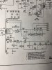
I hate to admit this but I think I screwed up again replacing the diodes, I do not know why I seem to get this so wrong so many times, it is like a mental block. I just put the 4007's in the pic shows how, I hope that with the Schematic someone can verify they are backwards. When I plugged it in the fuse blew and the yellow 200uf got hot and leaked, all in just seconds. I have ordered another nichicon radial to replace it. And things were going so well.
Attachments
s-petersen
Scott
I can't tell from the pic, but for the bios supply the stripe on the diodes points to the transformer, and the cap + is connected to the ground. It looks like the diodes are in backwards,the connection point goes to the cap - connection
Last edited:
That is where I always get confused, I have the black base connected to the blue(faded to greenish) trf wires, and the thin light grey stripe is going to ground. Hopefully I will be able to remember stripe to trf. Thank you for the quick help. ron
By the way this Bell 2440 has a wonderful sound.
By the way this Bell 2440 has a wonderful sound.
