• The move to the new server is done. There are some software and database maintenance updates in process. This has us passing the hat around to help out. We appreciate any donations. Seriously, even a dollar helps. The payment page may be found here - https://www.audiokarma.org/support.html

Pio SX-636 Stereo indicator lamp, other LEDs

JKent

Active Member
I'm working on a friend's SX-636 that he says works fine but some of the fuse lamps are out. I figure I may as well replace all of the lamps with new LEDs and probably do a recap while I'm in there. I watched some videos and read a bit but still have questions:
  1. One YouTuber said NOT to use an LED for the Stereo indicator. One respected seller agrees, another sells LEDs for the Stereo lamp in his kit. Any input appreciated.
  2. Regarding the fuse lamps. LEDs are available in a variety of colors but I think I want to keep an original look. The seller who recommended incandescent for the Stereo lamp said to only use incandescent or Warm White for the fuse lamps. He said the tint is in the receiver and using colored LEDs will make everything "too blue". Again asking for input based on experience.
While we're at it, the YouTuber said to leave the big caps alone, He said they're high quality and should be good. But they're OLD! I'm inclined to replace everything. The same guy said the 220uF Hitachi caps are awful and must go and I think another YT guy said the same. I figure why not just replace 'em all.

TIA for any guidance.

Kent
 
Register to hide this ad
Be careful with the dial pointer - they are very brittle and break easily. My advice on that would be to leave alone if lamp works.

I don't recall any big issues using an LED for the stereo beacon, though its been a few years. Have had one in my SX737 for maybe 8 years now. Problem using incandescent is that the stereo beacon looks a little dimmer than it's LED neighbors(Aux, Am, Fm, Phono etc.)

Considering the receiver is close to 50 years old now, I wouldn't think twice about replacing the big caps.

I would agree with that for the colors. You end up with a rich deep royal blue, very pretty, but less true to original appearance. Warm white is the way to go if you want closer to original look that has pop and is much brighter than incandescent.
 
Last edited:
OK. Still not sure about the stereo indicator. I replaced all the other lamps and will probably post a thread. Also re-capped the power supply board with caps I had on hand BUT I'm still unsure about the Stereo indicator. I have the LED that came with the kit, or I could go to my local electronics shop and buy a new incandescent. What's the problem with using an LED? DWOJO says to use incandescent but ebay seller peace.love.and.music uses an LED. Youtuber AH-fix-it says the other lamps are in AC circuits so no problem using an LED but the Stereo indicator circuit is DC and the electronics "don't know what to do with" an LED, even one with a resistor in series. He said these receivers are "not happy" with an LED in there, so always use an incandescent. Guess I'll put in a new incandescent IF I can find one. Otherwise I may just leave the old one and hope it lasts.
 
Warm white fuse lamps for the dial looks great. An LED for the stereo beacon should be fine if voltage and more importantly amperage matches origional. Dial pointer may need to stay incandescent to fit the housing. They are easy to replace but will require splice and solder with shrink wrap over the splice. It's not hard to open the housing, just be careful.
 
OK. Still not sure about the stereo indicator. I replaced all the other lamps and will probably post a thread. Also re-capped the power supply board with caps I had on hand BUT I'm still unsure about the Stereo indicator. I have the LED that came with the kit, or I could go to my local electronics shop and buy a new incandescent. What's the problem with using an LED? DWOJO says to use incandescent but ebay seller peace.love.and.music uses an LED. Youtuber AH-fix-it says the other lamps are in AC circuits so no problem using an LED but the Stereo indicator circuit is DC and the electronics "don't know what to do with" an LED, even one with a resistor in series. He said these receivers are "not happy" with an LED in there, so always use an incandescent. Guess I'll put in a new incandescent IF I can find one. Otherwise I may just leave the old one and hope it lasts.

There's a sound reason to be careful about not using a LED for the STEREO indicator. The LED requires much less current than the incan. IIRC the STEREO incan is 50mA (could be wrong, it's been a while) and I found that when installing a warm white frosted 3mm LED, I had to reduce the forward current from the typical 20mA to 2mA to avoid it being way too bright. At 2mA, can that be an issue for however the IC is designed? Hmm....maybe not. I've used just an LED at 2mA from an old IC before. But, I also know some older circuits may "float" high if the load is too high of a resistance. Sometimes, these old-school designs would even use a lamp load to stabilize some other function. I don't know enough about the inner workings of the old IC, I don't suppose to be an expert....
So, when I did my 636, I did the math for the STEREO incan, and figured out an equivalent resistance to match the 50mA load, I have a series resistor to set the LED to 2mA (remember, that's the "correct" brightness for the LED I have, which is super efficient warm white not from eBay, I buy bare 3mm LEDs) and a parallel resistor to set an additional 48mA of load, so the IC continues to see approx. 50mA.
 
So, when I did my 636, I did the math for the STEREO incan, and figured out an equivalent resistance to match the 50mA load, I have a series resistor to set the LED to 2mA (remember, that's the "correct" brightness for the LED I have, which is super efficient warm white not from eBay, I buy bare 3mm LEDs) and a parallel resistor to set an additional 48mA of load, so the IC continues to see approx. 50mA.
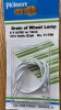
Thanks. That's a bit above my pay grade so I went to the local electronics store. The 636 Service Manual specifies a 6v 30ma lamp. I found these
IMG_0979.jpg
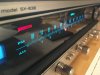
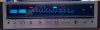
I was afraid they may be too dim but I think the results look good. Dial, needle pointer and FM indicator are all LEDs. STEREO indicator is incandescent.
IMG_0982.jpg
 
I did have 2 "scares" along the way. At first the Stereo indicator was constantly on. Turned out I had connected one wire to the wrong post. Dumb :mad: The other issue seemed to be with the Phono input. I hooked up an old TT, played a record and all was good but when I put the tone arm back in its holder, there was a loud buzz/hum! Fretted about that, sprayed some DeOxIt, poked around inside, then decided to sleep on it. Good choice. Next day I used a little black box reverse RIAA gadget to plug my iPod into the Phono jacks and it worked fine. The problem is apparently in the TT.
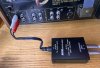
Aux to phono.jpg

btw--and this is a bit tangential but I'm really impressed with how over-built this thing is! Right down to the 15 (!) screws that hold the bottom panel on. And the caps, in this one at least, seem fine. I replaced the ones that were pretty easily accessible: The power supply board and the amplifier board. I had read that certain caps were "always" bad and should be replaced. Specifically, three 220uF Hitachi caps on the PS and some 0.33 Sanyos on the amp and other places. Don't know where this one is in the production run but all of the larger caps were Elnas and pretty much spot on, as were the little Sanyos. The farthest "off" were one 470 that measured 541 or about 15% high, a 100 that measured 77 (-23%) and a 220 that measured 253 (+15%). I don't think any of those are significant but I did replace all the caps on those 2 boards (about 15 in all). If I were more ambitious I would have replaced the transistors that have been identified as failure-prone but for now I'll just give it back to my friend (who's passing it along to his son) and wait and see.
 
Back
Top Bottom