• The move to the new server is done. There are some software and database maintenance updates in process. This has us passing the hat around to help out. We appreciate any donations. Seriously, even a dollar helps. The payment page may be found here - https://www.audiokarma.org/support.html

Pioneer A-70 Integrated Amp repair thread.

ItsGarand

Active Member
Update - SUCCESS!

I'd like to publicly thank the following AK members:
@QSilver , @The Fuxtor, @rcs16, @JoseHH, @LesE ,@markthefixer
For all the help and sticking with this tread for the last 4 months!

I'll post a thread/repair overview soon. See post #116 for overview


Gents, et al.

I Just acquired a non-operating A-70 Amp. My aim is to put it back into service. I have always had en interest in electronics - probably due to watching watching my dad put together his Heathkit amateur radio gear. You may recognize my handle as the guy that had a Pioneer A-77X. It also needed repair but being a sentimental piece, I had a professional do the repair. This A-70 means little to me and if I completely bork it I'm only out the few shekels I paid for it.

I'll be posting as I go and no doubt I'll be asking for help and advice.

It's a silver face amp and outward similar to the 77X but quite a bit different on the inside. I have the cover off and can see that somebody has been inside it before me. The legs on two of the power transistors have been pulled up. I guess that is a place to start.

So, bear with me, I'm a NUG.
 

Attachments

  • PXL_20211219_214009195.jpg
    PXL_20211219_214009195.jpg
    116.1 KB · Views: 124
  • PXL_20211219_214038795.jpg
    PXL_20211219_214038795.jpg
    127.6 KB · Views: 121
Last edited:
Register to hide this ad
Tonight, I unsoldered all of the power transistors and removed the heat sink from the chasis. After which I tested all of the power transistors.
I found that one of the 2SA1104 has given up the ghost. All of the others seem ok.
Now, to figure out this schematic. It's not nearly as modular and followable as the 77X to the untrained. in fact it's completely different inside.
I'll upload the service manual and put it in the docs section if it's not already there. It's too big for the post
 

Attachments

  • PXL_20211221_002625221.jpg
    PXL_20211221_002625221.jpg
    160.7 KB · Views: 58
  • InkedPXL_20211221_002633809_LI.jpg
    InkedPXL_20211221_002633809_LI.jpg
    132.3 KB · Views: 57
Ok guys, question time....
It looks like Digikey has a direct replacement for these obsolete transistors
2SA1104 -> 2SA1694 and it's complementary
2SC2579 -> 2SC4467

Would this be correct? I would assume that since I will have to replace the dead 1104 I would want to also replace it's complimentary 2579 Right?
For those of you that have delt with Digikey, would they Hfe match if I asked them, or am I going to have to buy a lot of them and do it myself?

I can't recall reading this anywhere, but did Pioneer do Hfe matching beyond the course grades of O, P and Y?

EDIT: I ended up calling digikey to inquire about hfe ranks since they don't have them listed as an ordering option. I had a nice chat with the gent there but he didn't know and will have to talk to the guys in the warehouse.
 
Last edited:
Gain matching output transistors is not required if you have emitter resistors - which the A-70 does. Emitter resistors force matching/load sharing so no worries there.

If you have one blown output transistor then you should replace the counterpart. However, this is not only an NSA amplifier, but it is an older generation compared to the A-77X and the NSA is not a chip - its a discrete circuit. Not only that, but it also has a Dynamic Power supply circuit. This incorporates another two transistors per channel on the output heatsink. These LOOK like the outputs and are exactly the same as the outputs BUT they manage power switching TO the outputs. Its another level of complexity added to the NSA design.

The amount of posts here on the NSA in various amps, with blown outputs is starting to make me think they're all reaching the end of the line in the original forms... and the driver transistor situation is still up in the air. I'm currently working on an A-7 - the previous generation to the A-70, an NSA without the dynamic power supply. Similar issues to yours, blown output. So far I've had to rebuild the whole amp channel as the damage (almost always) had reached back all the way to the pre driver stage - which isn't unheard of at all. Pioneer themselves predicted it on such a failure.

I'd say, if your replacing two, replace the whole lot. Might as well replace all of them now then doing one or two and then a year later having to pull that awkward heatsink back out to do the rest.
 
Gain matching output transistors is not required if you have emitter resistors - which the A-70 does. Emitter resistors force matching/load sharing so no worries there.

I'd say, if your replacing two, replace the whole lot. Might as well replace all of them now then doing one or two and then a year later having to pull that awkward heatsink back out to do the rest.

Very good information - many thanks for the reply.

As you have advised, I have already started looking for replacements for all of those transistors on that heat sink.

Perhaps I got lucky: Q1-4 are the power supply transistors (2SA1294 / 2SC3263) and Q6-8 are the dynamic power supply (2SA1104 / 2SC2579).

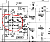
The 1104 in the red box below is the one that let go. All of the other ones test good on my meter. Those 4 resistors still measure .22
I guess I should be checking out all of the other transistors down stream from that 1104? Q45 etc....

The green box is the complimentary.

index.php
 
Interesting that the DPS (Dynamic Power Supply) has let go. If that's the case, you might need to follow back through the power supply circuit instead of the power amp circuit. I'll have to check through the notes on how the dynamic power supply fails. But, IIRC, I think that the transistors I recommended for the outputs of the A-77X should also work here too.
 
Interesting that the DPS (Dynamic Power Supply) has let go. If that's the case, you might need to follow back through the power supply circuit instead of the power amp circuit. I'll have to check through the notes on how the dynamic power supply fails. But, IIRC, I think that the transistors I recommended for the outputs of the A-77X should also work here too.
I'm thinking about also replace the drivers prior to the outputs. they are: 2SC2238 and 2SA968(Toshibas). What do you think about using the TTA004B and TTC004B as replacements? The form factor is a little different(TO-126n), but it looks like they will fit in the heat sinks. The rest of the parameters look like they they are equivalent and Mouser seems to have plenty of them.

Find anything in your notes?
 
Last edited:
The best choice which is NLA was the 2SC5171 and 2SA1913 - these had a speed of 200MHz in a TO-220 package. This matched the 2SC2275 (I think). That pioneer used.

However, Pioneer, before using those, used the 2SC1913 and 2SA913. TO-220 again, but the speed was 120MHz.

In this application using the TO-126 TTA004B and TTC004B attached to a small heatsink and possibly the same heatsink for thermal stability. Might work as I believe these two transistors are in the 100-120MHz range from memory. However, any slower will start to bring the amps very low distortion factor up significantly. I read this from one of MTF's posts on the rebuild of a SA-8800. You also have to check the saturation voltage, as the older transistors were around 1.2V. Some modern ones need a whole lot less - just 0.6V. This causes the bias circuit to turn on far too hard so getting this right saves a lot of problems readjusting the bias circuit to accommodate a transistor with a lower saturation point.

Vce on the TTs is .5 and Vbe is 1.5 and the Freq is 100Mhz
 
Yes, I've not tried these in an NSA yet so I'm not sure if they will work correctly. 100Mhz might be ok, but it might be a tiny bit too slow... MTF made a post about the importance of the driver transistors speed... I need to try and hunt it down again. They could be worth a try if you are up for it and have something to check the distortion figures with. That said, the first test would be to see if it would power up and bias correctly.
 
Well, I have all the new power transistors soldered in. I have the unit connected to a DBT and powered it up. And no surprise, the lights came on (a bit dim) and the speaker relays did not click on.
So, I thought I'd check some voltages coming off the power supply:

Starting with the ORANGE power supply output, shouldn't I see 75 and -75 volts at pins 39 and 40 respectively?
so, black lead on the chassis and red on the pin, I'm basically seeing no volts.

upload_2022-1-7_18-10-36.png
 
If you are measuring right at Pin 39 and 40, it'll be roughly 53V AC on each pin and double that if measured across Pin 39 and Pin 40. It'll only be 75V DC once it passes through the bridge rectifier diodes D60 - D63.
 
If you are measuring right at Pin 39 and 40, it'll be roughly 53V AC on each pin and double that if measured across Pin 39 and Pin 40. It'll only be 75V DC once it passes through the bridge rectifier diodes D60 - D63.

On pins 39 and 40(ORANGE) I have 50.6V AC and 61V DC past the bridge.
On pins 45 and 46 (RED)I have 31.3V AC and 37V DC past the bridge.
So, I guess that looks OK.

There is an 8A fuse for the outlets that seems to be missing so, I'll have to replace that. I don't have a clue as to what the original one looks like but it's not one of the smaller ones.
And one of the lights for the sliders on the front panel is toast.
Check for your +15v in the power supply. That runs those lights...
 
All lights are good now.

Since the speaker relays are not clicking I tested the outputs of the the voltage regulator/protector circuit (Pins 1 & 2) and the L/R channel outputs (Pins 5&6) which are inputs to the speaker switch assembly:

Pin 1: 34.87Vdc
Pin 2: 34.85Vdc
Pin 5: 47.92Vdc
Pin 6: 47.92Vdc

With no input signal, volume all the way down, muting off. I should not be seeing these voltages right?

upload_2022-1-15_15-4-23.png
 
They're not clicking because both the amplifier channels look to have "railed" basically this means the amplifier circuits have a problem which is causing them to not conduct properly. This makes the amplifier swing to one of the rail voltages on the output transistors and not balance to 0mV. Have you removed the driver transistors and tested those yet? If the output transistors were damaged, its very likely they took out other components behind them too. So starting with the driver transistors, we start hunting for the damage. Q27 - Q30 are the drivers. Two per channel.
 
They're not clicking because both the amplifier channels look to have "railed" basically this means the amplifier circuits have a problem which is causing them to not conduct properly. This makes the amplifier swing to one of the rail voltages on the output transistors and not balance to 0mV. Have you removed the driver transistors and tested those yet? If the output transistors were damaged, its very likely they took out other components behind them too. So starting with the driver transistors, we start hunting for the damage. Q27 - Q30 are the drivers. Two per channel.

I just pulled, tested, and resoldered Q27-Q30. They all looked good to me. Checked B->C, B->E All showed .6ishV. C->E 0L All reverse combos showed 0L.
Do we keep going backwards, or do we look elsewhere next?
 
Check them again, this time in circuit and post voltage readings on each pin. Emitter Collector and Base. Referenced to ground.

Also, check all regulated power supply voltages. This could be caused if a regulator fails too and it looses one of the drover stage voltage supplies.
 
Check them again, this time in circuit and post voltage readings on each pin. Emitter Collector and Base. Referenced to ground.

Also, check all regulated power supply voltages. This could be caused if a regulator fails too and it looses one of the drover stage voltage supplies.

Ok, getting into it Here are the values for the driver transistors: Using chassis as the ground...
Right Channel
Q28 (C2238)
  • B: 30V C: 31.83V E: 29.95V
Q30 (A968)
  • B: 27.9V C: -32.3V E: 28.58V
Right Channel
Q29 (A968)
  • B: 28.53V C: -32.33V E: 29.14V
Q27 (C2238)
  • B: 30.94V C: 32.15V E: 30.39V
Going through the power regulator getting interesting....
On Diodes D52/D53 I have 20Vdc
On Diodes D54/D55 I have -20Vdc

Transistors Q58 and Q59: Both of these (complimentary) are Darlingtons
For +/- 15V
Q58(D836A):
B: +501mV C: -200mV E: -550mV
Q59:
B:-14.7V C: -19V E: -15.65V

So I pulled Q58 and tested it:
B->C: .676, B->E: .830, C->E: 0L
Rev
B->C: 0L , B->E: 0L, C->E: .614 *** I would assume that this transistor is considered bad but it's a Darlington so is there any way to test these ?
 
Last edited:
I would assume that this transistor is considered bad but it's a Darlington so is there any way to test these ?

What makes you say that? The schematic doesn't seem to suggest so. Standard transistor as far as I can see. The transistor might be bad... but before you condem it, just check that R801 is indeed 15 Ohms. Sometimes these resistors are fusible and it may have popped. Usually they look fine so dont be fooled by its pristine appearance. Just check the resistance across it with the power off. Also make sure that all the zener diodes in that block are not shorted to ground.

upload_2022-1-16_21-16-44.png
 
Back
Top Bottom