Gerge_Sletar
New Member
Hello
I’m in need of some advice, I've been working on a pioneer A-X5 that is overheating after replacing a transistor in the left channel.
After much probing with a multimeter, the right channel output transistors and other components showed the correct voltage. Moving over to the left channel, I found 12v on one of the 2SA798 duo transistors, where there should be 0v. I followed the line back and tested transistors as I went. I got to the output transistors, and the base voltage should have been 0.6 / -0.6 but was showing much higher (I can't remember off the top of my head). Following down more, I came to transistor Q6 2SC2705/A/ took it out for testing, and it was completely dead, with no signs of life. I ordered a replacement from eBay.

Which arrived last week, soldered it in and turned everything on. The relay clicked, and I had sound.
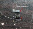
A new problem has emerged: the output transistors on the left channel got so hot in the minute, or so I had the amp on that the heat sink was hard to hold on to. Turning everything off very quickly to cool down, I inspected the new transistor (photo attached) markings where 2SC2705 Y markings. After looking on alltransistors.com, the only difference between the Y and the standard is the HFE, which is 120HFE on the Y and 80HFE on the minimum. Could this be the problem? I did some quick voltage testing with the new transistor while the amp was powered up, and all the voltage looked correct.
I was going to try to order a 2SC2705-O, which has identical specs on eBay, but the only UK supplier has told me they've run out.
If this is the case, does anyone have any suggestions on sourcing a replacement transistor?
I’m in need of some advice, I've been working on a pioneer A-X5 that is overheating after replacing a transistor in the left channel.
After much probing with a multimeter, the right channel output transistors and other components showed the correct voltage. Moving over to the left channel, I found 12v on one of the 2SA798 duo transistors, where there should be 0v. I followed the line back and tested transistors as I went. I got to the output transistors, and the base voltage should have been 0.6 / -0.6 but was showing much higher (I can't remember off the top of my head). Following down more, I came to transistor Q6 2SC2705/A/ took it out for testing, and it was completely dead, with no signs of life. I ordered a replacement from eBay.
2SC2705 Transistor Silicon NPN - CASE: TO92L MAKE: Toshiba | eBay
Find many great new & used options and get the best deals for 2SC2705 Transistor Silicon NPN - CASE: TO92L MAKE: Toshiba at the best online prices at eBay! Free delivery for many products.
www.ebay.co.uk
Which arrived last week, soldered it in and turned everything on. The relay clicked, and I had sound.
A new problem has emerged: the output transistors on the left channel got so hot in the minute, or so I had the amp on that the heat sink was hard to hold on to. Turning everything off very quickly to cool down, I inspected the new transistor (photo attached) markings where 2SC2705 Y markings. After looking on alltransistors.com, the only difference between the Y and the standard is the HFE, which is 120HFE on the Y and 80HFE on the minimum. Could this be the problem? I did some quick voltage testing with the new transistor while the amp was powered up, and all the voltage looked correct.
I was going to try to order a 2SC2705-O, which has identical specs on eBay, but the only UK supplier has told me they've run out.
If this is the case, does anyone have any suggestions on sourcing a replacement transistor?