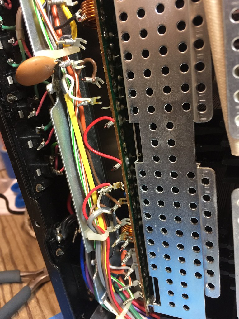
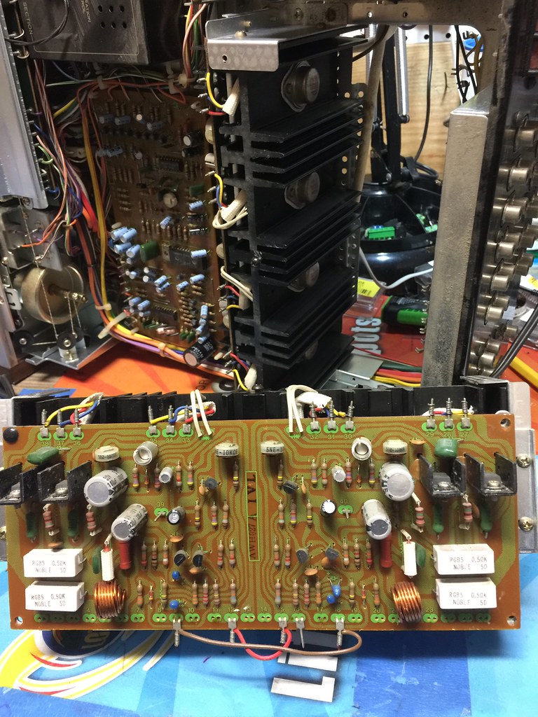
Hi I have this nice shape QX-949A where it is in Protection.
When I first got it to look over The relay would click after a long while and I was able to get a few DC measurements off the speaker Terminals but then its click out again going into protection.
I have the Service manual and need some guidance , first in naming the channels.
I measured the output voltages on the 3 output terminals of the power transistors and all but one measured in a similar voltage readings its the amp ,if looking from the front face, at the top right corner. the one in question measure over 39 volts at all pins IIRC as I did this latte last night.

The service manuals lines indicating the parts is faded and you can not make out what description goes to
what part.
So On that amp the readings across pins 1 and 2 was .5 volts way above the 20mV's it needs to be adjusted to.
Adjusting VR3 got me to 240Mv's but it was jumping around as I tried sometimes hitting 3 volts dc.
So something is amiss on that amp section possible. Where do I begin diagnosing this?
I did a diode test of the output 's and all seem to measure ok , this was done in circuit for now. Removing them right now seems a task I'll wait for till they actually need to be removed.
Athanasios
When I first got it to look over The relay would click after a long while and I was able to get a few DC measurements off the speaker Terminals but then its click out again going into protection.
I have the Service manual and need some guidance , first in naming the channels.
I measured the output voltages on the 3 output terminals of the power transistors and all but one measured in a similar voltage readings its the amp ,if looking from the front face, at the top right corner. the one in question measure over 39 volts at all pins IIRC as I did this latte last night.
The service manuals lines indicating the parts is faded and you can not make out what description goes to
what part.
So On that amp the readings across pins 1 and 2 was .5 volts way above the 20mV's it needs to be adjusted to.
Adjusting VR3 got me to 240Mv's but it was jumping around as I tried sometimes hitting 3 volts dc.
So something is amiss on that amp section possible. Where do I begin diagnosing this?
I did a diode test of the output 's and all seem to measure ok , this was done in circuit for now. Removing them right now seems a task I'll wait for till they actually need to be removed.
Athanasios
Last edited: