• The move to the new server is done. There are some software and database maintenance updates in process. This has us passing the hat around to help out. We appreciate any donations. Seriously, even a dollar helps. The payment page may be found here - https://www.audiokarma.org/support.html

Pioneer SA-1000 keeps burning R1 330ohm on power supply

Brownie Mix

New Member
Hey all,
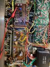
So after full recap and all new transistors this Pioneer SA-1000 keeps burning R1 330 ohm on the power supply board. (You can see the toasty resistor in pic) I’ve double checked multiple times all transistors oriented correctly. Caps oriented correctly. I think I might have a ground short somewhere because pin 13 is grounded out and 14 for that matter. Any ideas? Thanks!
 

Attachments

  • IMG_0907.jpeg
    IMG_0907.jpeg
    356.7 KB · Views: 62
  • IMG_0907.jpeg
    IMG_0907.jpeg
    359 KB · Views: 61
Last edited:
Register to hide this ad
Can you move the cap that's tied to what looks like a terminal strip and get it off the pins of that other board? I know it has a sleeve over the metal can (UPW?), but does it need to be resting on it?
 
Have you removed the power transistors?
Make sure none are shorted to the heat sink.
Yes, I have removed them and still smoking resistor.
When I remove the leads on pin 1 and 3 on the protection (for adjusting voltage per service manual) the relay will click when I adjust to 0v but still burns resistor. when I put them back on the pins it doesn't want to adjust with the VR
 
Can you move the cap that's tied to what looks like a terminal strip and get it off the pins of that other board? I know it has a sleeve over the metal can (UPW?), but does it need to be resting on it?
I will double check that this evening. I'm pretty sure that it wasn't resting on it but that is a good point
 
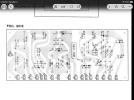
The large blob of solder above the capacitor by the resistor looks suspicious. Now look at the bottom side trace paint markings. The bottom orange wire goes to the trace that follows above the horizontal diode to the positive side of the single electrolytic cap and the other 2 diodes and ceramic caps. The black wire (#12) goes under the resistor and diode then above the single electrolytic cap curving down around the two electrolytic caps to their positive side. The red wire (#13) goes under the diode, to the resistor then past the solder blob to the negative side of the 2 electrolytic caps. The orange wire (#14) goes to the diode cathode side and thru to the negative side of the single cap and the resistor. Without looking at the schematic, I believe that the two electrolytic caps on the fer left are backwards. I base my opinions on normal wire color code conventions where the red and orange will have a positive potential and the black wire should have a negative potential.
 
Last edited:
Can you post the schematic and board layout from the service manual? There are a few versions of the "SX 1000." I recently worked on the 1000tw and it's easy to mess up the layout of the transistors because the board is so hard to read.
 
I think the title is incorrect...it appears he's working on an SA-1000 integrated amp. The board layout in the pics definitely isn't the SX-1000.
 
The large blob of solder above the capacitor by the resistor looks suspicious. Now look at the bottom side trace paint markings. The bottom orange wire goes to the trace that follows above the horizontal diode to the positive side of the single electrolytic cap and the other 2 diodes and ceramic caps. The black wire (#12) goes under the resistor and diode then above the single electrolytic cap curving down around the two electrolytic caps to their positive side. The red wire (#13) goes under the diode, to the resistor then past the solder blob to the negative side of the 2 electrolytic caps. The orange wire (#14) goes to the diode cathode side and thru to the negative side of the single cap and the resistor. Without looking at the schematic, I believe that the two electrolytic caps on the fer left are backwards. I base my opinions on normal wire color code conventions where the red and orange will have a positive potential and the black wire should have a negative potential.
69Bee, Im away from it toady but will look over that this evening. thanks.
I think what looks like solder blob is actually old glue that is reflecting light.
I know the screen printing on the boards for that cap placement shows + and I have them in correct but will look again.
This thing has me puzzled
Can you post the schematic and board layout from the service manual? There are a few versions of the "SX 1000." I recently worked on the 1000tw and it's easy to mess up the layout of the transistors because the board is so hard to read.
Pioneer SA-1000. Sorry about that. It will not let me edit the title
 
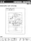
Look at the full schematic at the PS board. You will see that pins 1 & 12 go to ground. Capacitors C8 & C9 from pin 1 (GND) are shown correctly with the negative side of the caps to gnd P1 but the caps C3 & C4 are shown backwards with the positive sides to gnd P12. C3 & C4 need to be reversed to stop nuking the resistor. I would check them first to see if they are hurt or just replace them when you get another resistor.

EDIT: Well I see why they are like that. I downloaded the manual so I could blow it up and pin 13 is -45 volts and that would make ground more positive and that is why the caps are reversed for C3 and C4.
 
Last edited:
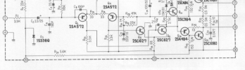
Pin 13 feeds pin 23 on the amp board. Check the amp board for shorts in that part of the circuit. Also ensure that D5 isn't shorted . ..

1772497713148.png
 
The dim bulb dims down fine but still burns resistor. I also have the output transistors pulled out of it. It was doing it with them in there too, but I just pulled them out to keep them safe.
 
Pull the wire from 13 and see if the situation changes. It should have no current draw worth talking about with it off but lets confirm.

Also can you give us the voltage drop across the 330 ohm resistor?
 
gadget73
Yes I will do that this evening. I will need to move quick because that resistor heats up very fast. but should be able to do it.
thanks!!
 
Back
Top Bottom