• The move to the new server is done. There are some software and database maintenance updates in process. This has us passing the hat around to help out. We appreciate any donations. Seriously, even a dollar helps. The payment page may be found here - https://www.audiokarma.org/support.html

Pioneer SA 6300 smoke generator

maxProview

Member
Good morning,
I saved an SA6300 from the landfill but it gives me a lot of worries!
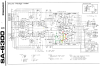
There is no service manual for this model... So I identified the components from the schematic and the PCB.
The protection circuit had been shunted (Q101 and Q102 are out of order but D1 is ok).
FU3 or FU4 burns immediately at startup and then R66 begins to smoke.
I suspected C52 but it seems OK. I continued and tested D13 and the Q5 and Q7 couple which are also good!
Remaining only in my opinion Q9 as a possibility I also tested it and it is also good!
I'm so lost...
If anyone has an idea that would be great!
Thanks in advance


Update : The transistors look good to the tester. Without Q9 the amp is stable (the fuses do not burn and no smoke on R). With Q9, the fuses burn immediately. I replaced it with a BD139, the result is the same !
 
Last edited:
Register to hide this ad
I am unaware of your level of expertise... so forgive me...

The protection circuit is an abomination, a crowbar circuit designed to short the +26v to the -26v through D101 and R106 (0.5 Ω 2W) and pop the fuses.
All because they didn't want the expense of a relay connecting and disconnecting the speakers to prevent house fires.
Remove D101 (The triac) or R106 (0.5 Ω 2W, may be easier to find) for now, to be sure that protection operation isn't your culprit.

The amp will dc balance with the drivers, so outputs are not a necessity for trouble shooting.. That gets the power amp down to 5 transistors.
2x ksa992, 2x ksc2383 & 1 x ksa1013

Q5 & Q7 diff amp get input and feedback from the output,
use that to drive Q9 to an appropriate conductance
to place the Q11 driver base at +1.2v and the Q13 driver base at -1.2 v.resulting in 0.000v at the junction of R68 & R70 (150 Ω) of the Q11 & Q13 outputs
interrupt that teeter-totter and it slams to the positive or negative rail as Q5/Q7 cannot drive Q9 to achieve those voltages.
Either it cannot turn ON Q9 hard enough, or turn OFF Q9 hard enough.

Q9 is powered by bootstrap current generator C46, which ensures that there is always 24v greater than the output voltage flowing current through R60 (4.7 kΩ)
for 5 milliamps of current, through the R64 & R62 & D3 & D5 (the stv thermal diode) getting those magic +1.2v and -1.2v.
Q9 itself has a 1 Ω emitter resistor, but at 5 milliamps, that's only 5millivolts...

Check the 150 Ω and 0.5 Ω emitter resistors. They are the only points driving the output, to 0.000 volts and they have to balance to get there.


upload_2023-5-25_21-49-54.png
 
Good morning, First of all thank you for all these explanations. I'm starting to get interested in amplifiers and this is only the fourth on which I look! I confess that I did not understand all of your explanations. First of all, I understand that I can operate the amplifier without Q14 Q15 Q16 and Q17 because the amplifier consists of 2 final stages. So I'm going to start by dismantling these power transistors.

Without these transistors, for me, the amp will consist on two SA763, two SC1318A, one SA720.

Sorry, but i don't understand well this part : "
interrupt that teeter-totter and it slams to the positive or negative rail as Q5/Q7 cannot drive Q9 to achieve those voltages.
Either it cannot turn ON Q9 hard enough, or turn OFF Q9 hard enough. "

I have already tested R76 and R78, I will test R68 and R70.
 
Bold type is for Marks quotes only. No other significance is inferred.
Simplified version:
1) Protect circuit: Remove D101 for now, to be sure that protection operation isn't your culprit. Quote: MTF (Mark The Fixer Post #2).
2) Check the 150 Ω and 0.5 Ω emitter resistors. They are the only points driving the output, to 0.000 volts and they have to balance to get there.
R70 150ohm, R68 150ohm, R78 0.5ohm and R76 0.5ohm. Quote: MTF (Mark The Fixer Post #2).

3) You can run it without the outputs connected. When you get the amp balanced and voltages checked you can reconnect them. Quote: zebulon1 Post #4.

Build a DBT (Dim Bulb Tester) https://audiokarma.org/forums/index.php?threads/dim-bulb-tester-build-and-how-to.808399/
Learn its use. A must in this hobby.
HiFiengine.com has the service manual if you can sign in. I heard their membership is full?
 
Last edited:
Hello

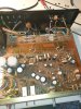
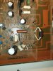
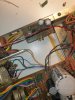
some news and photos of the amplifier. I have dismantled the power transistors (without the same resistor, it still smokes on start-up). I tested the 4 resistors and they are all ok.

Another clarification, the protection circuit has been completely disconnected

I noticed that the voltage behind R52 is high! 0.8V instead of the expected 0.6V. on the working channel the voltage is indeed 0.6V. R22 is correct.
 

Attachments

  • 20230529_211457.jpg
    20230529_211457.jpg
    153 KB · Views: 12
  • 20230529_211503.jpg
    20230529_211503.jpg
    151 KB · Views: 11
  • 20230529_211516.jpg
    20230529_211516.jpg
    128.2 KB · Views: 13
Last edited:
Back
Top Bottom