• The move to the new server is done. There are some software and database maintenance updates in process. This has us passing the hat around to help out. We appreciate any donations. Seriously, even a dollar helps. The payment page may be found here - https://www.audiokarma.org/support.html

Pioneer SA-7500 II, right channel signal clips if the volume is turned up.

Moncho

Member
Hi guys,

I have a Pioneer SA-7500 II with a defective right channel, I see the signal is clips and distorts, when I turn up the volume.
The first thing I did was to clean all the amplifier controls with contact cleaner, but the fault persisted. So, to identify where the problem is I have injected a 1KHz signal through the Aux input and measured at test points T46 and T48, which correspond to the output of the preamplification stage. At this point the signals are identical, so I have assumed that the problem is further downstream in the amplifier stage.
I made more measurements and the signal begins to present problems when increasing the volume at the base of Q4, which is a “differential” chip (I think) that contains two transistors inside. I have thought that this chip is responsible, so I exchanged the right channel chip with the left channel chip, hoping that the problem would now occur in the left channel, but it was not. Continue measuring and everything looks fine, the capacitors are fine, the transistors are fine.
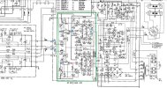
Because of this I decided to apply brute force and have swapped, in the amplification stage (enclosed with the green box in Diagram1), all the components (but the resistors) of the right channel with the components of the left channel, one by one hoping to identify which component is causing the problem. But I have had no luck, the problem remains in the right channel. All these measurements and tests were done using an 8 ohms dummy load on each channel. Then it occurred to me to measure without load, so I removed the 8 ohms dummy load and measured at the output of the speakers, and the signals are identical !!!! :oops:

In short, the right channel only distorts the signal if it has a load connected and if the volume is turned up.
I thought it could be the relay, I have disassembled it but I have not been able to open it, I feel like I am going to break it, this is not the original (I think), but it looks in good condition (it has a transparent cover and you can see the contactors through it).

Could you please guys help me identify where the problem is?

In the attached photos:
Diagram1: In blue is marked where the signal is correct and in red where it is clipped. The green box indicates the area where the components have been swapped from one channel to the other.
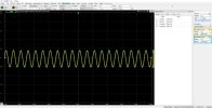
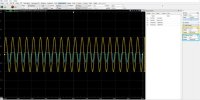
The other photos have descriptive names of the measurements made with my oscilloscope.

Thanks and have a nice day.
 

Attachments

  • Diagram1.JPG
    Diagram1.JPG
    132 KB · Views: 13
  • With_Load_at_T46_and_T48.JPG
    With_Load_at_T46_and_T48.JPG
    61.7 KB · Views: 14
  • With_Load_at_Speakers_Terminals.JPG
    With_Load_at_Speakers_Terminals.JPG
    70.9 KB · Views: 11
  • Without_Load_at_Speakers_Terminals.JPG
    Without_Load_at_Speakers_Terminals.JPG
    73 KB · Views: 14
Register to hide this ad
Generally:
Measure the base voltage at the outputs and make sure they are acting together when operating the volume.
There maybe a unregulated voltage issue. Leaky filter for the positive rail? Failed rectifier? Poor connections?
Use the good channel for comparison.
 
Last edited:
Measure the base voltage at the outputs and make sure they are acting together when operating the volume.
There maybe a unregulated voltage issue. Leaky filter for the positive rail? Failed rectifier? Poor connections?
Use the good channel for comparison.

Hi Zebulon,
thanks for your reply.

Measure the base voltage at the outputs and make sure they are acting together when operating the volume
What do you mean? Do you mean a DC offset in each speaker output?

There maybe a unregulated voltage issue. Leaky filter for the positive rail?
how could they only affect one channel?

Thanks again :)
 
The base voltages at the outputs should be equal but the are opposite in polarity. They should move equally as the volume is operated and move in conjunction.
Watch the good channel and see what its supposed to look like.
Two meters is nice but if you know the voltage delta between them you can connect the single meter leads on each base. Measure and watch the voltage. One lead on the positive base and the other lead on the opposite negative transistor base.
I agree about the unregulated - if the unregulated is shared between the amps. You could measure the output collectors making sure they are getting the same +- voltages?
Still look for bad connections. torn solder pads etc..
Excuse the general discussion. I'm at work between jobs.
 
Last edited:
The base voltages at the outputs should be equal but the are opposite in polarity. They should move equally as the volume is operated and move in conjunction.
Watch the good channel and see what its supposed to look like.
Two meters is nice but if you know the voltage delta between them you can connect the single meter leads on each base. Measure and watch the voltage. One lead on the positive base and the other lead on the opposite negative transistor base.
I agree about the unregulated - if the unregulated is shared between the amps. You could measure the output collectors making sure they are getting the same +- voltages?
Still look for bad connections. torn solder pads etc..
Excuse the general discussion. I'm at work between jobs.
Hi again,

I just took the suggested measurements and here are the results.

QVolume level
0 clicks3 clicks7 clicks10 clicks / 9:00 o'clock
(clipping)
16 clicks / 12:00 o'clock
(clipping)
Q16
1,11​
1,27​
3,47​
7,74​
11,75​
Q14
-0,13​
-0,18​
-0,23​
-0,14​
-0,22​
Q13
-0,72​
-0,72​
-0,72​
-0,72​
-0,72​
Q15
0,78​
0,78​
0,78​
0,78​
0,78​

So, the left channel (the good one) shows no changes but the right channel (the bad one), his Transistor Q16 starts to se an increment in the base Voltage, while his pair, Q14, keeps his voltage "fairly" stable.

@zebulon1: With this data ... do you have an idea of what is causing the issue? I have been looking for bad connections or soldering, but haven't found anything yet.
 
@zebulon1
Looking for bad connections or soldering. I start to tap the PCB and components, shake a bit the cables while the signal was clipping and it stays rock solid, no changes at all, so it has to be a component, right? ... Could a cap or the relay cause this kind of issue in just one channel?

Any idea is welcomed, because I have none ... My next move is buy another relay? replace all diodes and caps? ... after that I have nothing, I'm dead in the middle of the sea.
 
Curious.
Have you checked the DC Balance (Offset) and the idles.? It must be okay as its not in protection.
Have you checked the emitter resistors? in the bad channel? The resistors between the test points near the outputs. Should of had you check those first.
Q14 is not seeing a input signal. Check its driver (Q10?) and the connections to them.
Your doing well. Its not caps or diodes. Emitter resistors or a bad signal to the base of Q14.
You swapped transistors with no help. Your close to finding the problem.
Use your meter in continuity and check those connections on the traces between the transistors. I don't have a schematic to look at other than the blurry one you posted. Not your fault.
 
@zebulon1
Have you checked the DC Balance (Offset) and the idles.? It must be okay as its not in protection.
yes and it's ok, as you said, it's not in protection mode.

Have you checked the emitter resistors? in the bad channel? The resistors between the test points near the outputs. Should of had you check those first.
Yes I did, when I swapped them also measured them.

Q14 is not seeing a input signal. Check its driver (Q10?) and the connections to them.
I'll check the signal at Q10 emitter leg and compare it with the other channel Q9. But it's not the transistor, because they were swapped. The path from Q10 emitter to Q14 base, should be ok, otherwise it would not have any signal at any volume level, but at low volumes there is a perfect signal at the speakers output. But I'll check it ;)
Use your meter in continuity and check those connections on the traces between the transistors. I don't have a schematic to look at other than the blurry one you posted. Not your fault.
Good hint, I'll check all paths and traces. I have attached the service manual.

I'll do the new measurements tomorrow, I live in Germany and it's late or the wife it's saying somethin like that hahaha

Thanks again.
 
The top half of the sign is missing.
That would be Q16, it’s responsible for that half.
Take a good look and using your meter check all the trace connections.
 
Hi @zebulon1
I have completely discarded per-amplification and protection circuit. I have swapped the pre-amp stage outputs and no change, then took off the relay and solder some wires to the tabs and the solder them swapped the left with the right channel to the PCB, no changes. So it is the power amplification stage and now I'm checking every trace.

Thank a lot for your hints, as soon as I find something I'll let you know. After all if I repair it the half of the credit will be yours :D

Have a nice day.
 
Hi @zebulon1,

I have found the error and it was just in front of the mirror. I'm ashamed to realize how poor my judgment was at the moment to omit critical information related to the problem I was facing. I just dismissed it, because didn't think it was relevant. I should have started saying that the power output transistor in the right channel were not the original model, so the left has original output transistors and the right does not. Then I swapped "everything" except those transistors, because they are attached to the heatsink and soldered directly in the pcb, so remove them it's a "big task", that was a second big fail from me. Then traying to find the issue I made a mess and burned some components. I replaced them and start over, I have found also an error in the silkscreen on the circuit board where D4 and D6 are swapped, but it had no impact in the overall behavior.

Now ... when I realized how stupid I was, it came to me. So I have changed the emitter resistors for that channel R58 and R60 from 0.5 to 5 Ohms and now it clips, but much later (12 Watts RMS, which is loud enough to me), then I have changed them again from 5 to 10 Ohms, but do not see any improvement. So now my question is, what other change do I have to make to have the two channels clipping at the same power output? The left channel with the original design clips just over 40 Watts. The output power transistors that I'm using now are Q14 -> 2SA1943N and Q16 -> 2SC5200N.

Thanks again and I'm sorry, I have made you lost your time but I have learned my lesson.
Have a nice day.
 
@zebulon1
I have fixed it !!!!
The problem were the rectifier diodes, I have started from the beginning and realized that in the rectification bridge were signals of overheat. I took off the diodes and they were literally broken in half (picture attached), but at the bottom, so you could not see them easily. So I changed them for these ones RGP30M-E3/54.
Now the voltages at the test points for the bias current for both channels are in range (measured after 30 minutes on), the right channel 37mV and left 57mV. It is possible that some transistors in the power stage are slowly drifting away from their original gain values, but still in range.

As result both channels follows the signal equally and the distortion starts at 66 watts RMS !!!!
If a square signal is injected, both channels show the same oscillation, which is very low.

Afterwards, I have also changed, in the power amplification stage, other resistors that should support 1/2 watt or more for new metal oxide resistors (all those that were mounted in height and that look bigger and wider than the others).
Almost all electrolytic capacitors were changed following the recommendations of this restoration restoration. The only ones I haven't changed yet are the power supply capacitors, because the modern ones (KEMET ALF70C103DD063) use “press-fit” and therefore I plan to design a small PCB to mount them there and then connect them to the existing terminals. This way I can also give them some height using brackets and take advantage of the mounting bracket with the existing heatsink.

So far I am very happy with this amp, it sounds great. I just want to solve the left channel bias current which is near the upper limit but is not urgent. I have also bought the replacement of all the diodes, but I will do that in the future. My idea is to leave this amp ready to enjoy it for many years without worries.

Thank again for all your recommendations and I can finally enjoy this beautiful amp. I don't understand how other people can talk bad about it, for me it sounds great. Now I am curious and I'd love to put my hands on a sa-8500II which is dual mono inside, but .... now I'm just happy :)

Have a nice day !!!!
 

Attachments

  • bad_diodes.JPG
    bad_diodes.JPG
    104.6 KB · Views: 5
Back
Top Bottom