• The move to the new server is done. There are some software and database maintenance updates in process. This has us passing the hat around to help out. We appreciate any donations. Seriously, even a dollar helps. The payment page may be found here - https://www.audiokarma.org/support.html

Pioneer SA-7800 - Help replacing transistors!

OK,
I finally "rehabilitated" the RIGHT channel too.
... and:
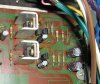
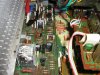
1) I recapped the power amp board (only 2 e-caps now!);
2) I made the adjustments according to service manual.
Again... the adjustment was a real PITA, voltages swinging quite a lot... Finally, I achieved relatively stable values +/-0.5mV around the figures mentioned in the service manual.
3) I took some pictures (see attachment);
4) Tested with the CD-player and it sounds ok. :music:
(that start-up little fart on the right channel has disappeared!).

TODO LIST:
1) Recap power board
2) Recap tone control board
3) replace output transistors
4) pilot lamp LED conversion
5) dunno... :scratch2: (clean&lube pots and switches...?)
 

Attachments
  • IMG_1649.jpg
    IMG_1649.jpg
    125 KB · Views: 129
Last edited:
Looks good!! :thmbsp:

Yup! And... sounds good too! :yes:
BTW: That relay... I can barely hear it when it clicks... (and now the top cover is off!).

@ leesonic :
Lee, as far as you remember, those big e-caps in the power supply (8200uF) were plug&play? ... or you had to drill the PCB in order to fit them?

[EDIT]:
Ok, Lee confirmed: I won't get rid of drilling... The new e-caps have ONLY 10mm lead space! Man, I hate drilling holes in the PCB :(
 
Last edited:
Hmmm,

I've encountered a problem when recapping PS board GWR-112:
In the service manual there is a jumper on the left side of C34 (see page 20).
Now, on the real board I found a capacitor there: 4.7uF/50V (same as C34)...

For the moment I put a jumper there (see the red circle in the attached picture).
Yet, I'm not sure... The marking on the PCB in that place is for a polar capacitor!!!

So, what should I do now?!?
1) leave that jumper as per service manual.
or
2) put a 4.7uF/50V as initially existed on power supply board ?
 

Attachments

  • pic_01a.jpg
    pic_01a.jpg
    133.2 KB · Views: 93
Last edited:
Hmmm,

I've encountered a problem when recapping PS board GWR-112:
In the service manual there is a jumper on the left side of C34 (see page 20).
Now, on the real board I found a capacitor there: 4.7uF/50V (same as C34)...

For the moment I put a jumper there (see the red circle in the attached picture).
Yet, I'm not sure... The marking on the PCB in that place is for a polar capacitor!!!

So, what should I do now?!?

WHAT were the markings UNDER what you are calling C34? The cap between the two small to-92 transistors? There is a trace between D32 cathode and q34 emitter that has a jumper and a capacitor (C34) in it. Maybe the assembly persons way back when got confused - the jumper and the cap. That's what it looks like to me. If the jumper is replaced by ANOTHER capacitor - the only effect would be to half the capacitance and double the voltage IF they were hooked + to - , now if the caps were hooked + to + or - to - THAT would make it a bipolar capacitor with no polarity sensitivity.

so leave it as you had it set up during the picture.. BUT to make it like the service manual, you have a cap where the jumper is shown in the manual, and jumper where the cap is shown...
 
Last edited:
... BUT to make it like the service manual, you have a cap where the jumper is shown in the manual, and jumper where the cap is shown...

I did it exactly like in the service manual... I checked that 4 times!
The jumper is closer to the Zener diode (and the edge of the board), while the capacitor is closer to the transistor(s) group.

Markings under the C34 capacitor are for a polar capacitor. And, of course, I followed exactly the polarities.

As a conclusion, I initially had TWO 4.7uF in series (connected + to -)!!!... making it 2.35uF/100V... probably a mistake I dare to say?
 
Last edited:
Ok, so today I managed to move forward:
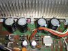
I recapped both tone-control and power-supply boards.
I took some pics (see attachment).

Tomorrow, I plan to do the LED conversion for the power-on indicator.
And probably I will try to replace the output transistors (Sankens)... if time allows...

BTW: I powered up the amp after mounting & soldering the big (8200uF) e-caps of the power supply (NO drilling :thmbsp: ).
Well, I kept the jumper (as seen in my previous post) and it seems the amp operates just fine :yes:
 

Attachments

  • IMG_1659.jpg
    IMG_1659.jpg
    124.9 KB · Views: 121
  • IMG_1664.jpg
    IMG_1664.jpg
    126.2 KB · Views: 107
Last edited:
Ok,
LED conversion done. No flickering, nice warm white!
(see attached pic).

Hmmm...
One question about the big e-caps (8000uF) in the power supply:
It seems one pair of them has a discharge resistor (R97 = 10Kohm), while the other pair doesn't have a discharge resistor... Why ?!
I'm not an expert, that's why I better ask... :scratch2:
I'm sure there must be an explanation for that.
 

Attachments

  • IMG_1661.jpg
    IMG_1661.jpg
    85.5 KB · Views: 79
Last edited:
Extremely BAD news...
Those Sanken output transistors do NOT fit, as they are much BIGGER than original outputs! :drool:
So, for the moment I'm stuck... I'll have to see if I can find an alternative to get out of this mess...
For those who recommended Sankens: Sorry folks, but at least for SA-7800 they won't work/fit! :thumbsdn:
 
Sanken 2sc3264/a1295 in the mt-200 package matches the Savantec spec for the 2sc2525/a1075 in the same mt-200 package.
Sanken 2sc2922/a1216 match as well
What Sanken parts do you have?
I am not too surer about the reason for the ecap bleed r only being on one side.
 
i had to cut the pcb on my 8800 to fit the larger transistors ..there was just enough room to do it .. not an elegant solution but doable
 
Sanken 2sc3264/a1295 in the mt-200 package matches the Savantec spec for the 2sc2525/a1075 in the same mt-200 package.
Sanken 2sc2922/a1216 match as well...
Oh, forget about sankens... I'm too pissed off to talk about that!
I just wanna rebuild the poor amp, not to demolish it... :(

I am not too surer about the reason for the ecap bleed r only being on one side.
Yup, that's why I asked... maybe some AK guru can "enlighten" us...? :)

@ 2petehall:
i had to cut the pcb on my 8800 to fit the larger transistors ..there was just enough room to do it .. not an elegant solution but doable.
Yup, I know exactly what you mean! Damn crap sankens ruin my (yester)day! :thumbsdn:
 
Last edited:
damn... I LET that Sanken reference THROUGH!!! and sadly, I was the one that TOLD you about the less expensive Ampslabs source, NOT REALIZING they wouldn't FIT!!! Grrrrrr....
Here's what I was looking for: the sideways mount (granted it is a SA-7800, not a 6500ii :D )....

Well, we BOTH read leesonic's thread, and didn't connect with the picture...


(what's with those brackets? I don't remember what they mount... can they be trimmed to fit??)

SA7800-10.jpg
 
Last edited:
Well, I won't use those sankens anymore... (they are history now).

Not sure yet what replacements I will choose for outputs (uncle Nick used Toshiba 1301 & 3280 ).
I'm in "low budget " status for the moment. Hence my decision is postponed for at least 1 week.

ANYWAY, Mark if you can give me a good advice regarding my main concern right now:
Should I put a discharge resistor for the other ecaps in the power supply or not? See my previous posts...
ONLY ONE group of ecaps has a discharge resistor R97=10kohm!
I don't like them charged while working on boards... you know what I mean (accidental sparks & smoke).
 
Last edited:
Well, I won't use those sankens anymore... (they are history now).

Not sure yet what replacements I will choose for outputs (uncle Nick used Toshiba 1301 & 3280 ).
I'm in "low budget " status for the moment. Hence my decision is postponed for at least 1 week.

ANYWAY, Mark if you can give me a good advice regarding my main concern right now:
Should I put a discharge resistor for the other ecaps in the power supply or not? See my previous posts...
ONLY ONE group of ecaps has a discharge resistor R97=10kohm!
I don't like them charged while working on boards... you know what I mean (accidental sparks & smoke).

That's because the indicator assembly on the positive polarity is a continuous power draw that will pull it down - BUT with yours removed, there IS NO DRAW *!!
* except for the static low power amplifier draw when idle current can't happen.

Thus the 10k resistor is needed only on the negative side when the unit is intact.

and yes you can add another on the positive side, it won't hurt much to add one there.
 
That's because the indicator assembly on the positive polarity is a continuous power draw that will pull it down - BUT with yours removed, there IS NO DRAW *!!
* except for the static low power amplifier draw when idle current can't happen.
...

Thanks Mark!
I've completely forgotten about the FL display!

BTW: I think there are some errors in the service manual !
Page 20 - BOARD CONNECTION DIAGRAM:
INDICATOR ASS'Y :
- Pin #5 -> wired incorrectly !!!
- Pin #4 -> wired incorrectly !!!
- Pin #3 -> not wired at all ??? Levitating !?!
If I am right, then this may lead to a dangerous situation, as pins 4 & 5 are the display board power pins.
 
Ok,
I decided to buy OnSemis for outputs: MJL1302 & MJL3281 (got them today).
Now I regret I didn't buy Toshiba 2SC5200 & its complementary from mouser... It could have saved some time and money...

Tomorrow - if time allows - I will try to fit the OnSemis on the heat-sink.
Wish me luck!
I'm afraid I will have to reposition one (or both?) STV-2H diodes...?
 
Ok,
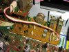
Today I managed to mount/fit the outputs !!! :thmbsp:
Check-out the attached pics!

No problem at all !... No drill, no extra holes needed! :nono:
Just plug-in, as I used the existing holes of the original outputs!

I must admit I made a huge mistake when I bought those Sanken's... :thumbsdn:
I should have listened to Lee...!


I was afraid I will have to reposition the STV-2H diodes...
Nope! The STV diodes didn't require any extra drilling / hole(s) ! :nono:

I made the idle current adjustment (again).
Then, I measured the DC offset:
- 14 mV on LEFT channel
- 24 mV on RIGHT
I suppose it's ok, right?

After that, I connected a CD player and hit "PLAY"...
Well, I am VERY IMPRESSED :tresbon:
Extremely good sound quality ! Just great!!! :music:

!!! AWESOME !!!
 

Attachments

  • IMG_1669.jpg
    IMG_1669.jpg
    162.8 KB · Views: 156
  • IMG_1668.jpg
    IMG_1668.jpg
    145.3 KB · Views: 153
Last edited:
Back
Top Bottom