• The move to the new server is done. There are some software and database maintenance updates in process. This has us passing the hat around to help out. We appreciate any donations. Seriously, even a dollar helps. The payment page may be found here - https://www.audiokarma.org/support.html

Pioneer SA-7800 with burnt out resistors

you did not recap the protection? DO IT!!! they are classic 0.22 uf o/c cap symptoms...(since the transistors q27 & q28 have been replaced)
(loss of capacitance or increased leakage at higher voltages)

c21, c22 0.22 uf stacked film caps... IMPORTANT!!!
c25, c26 upw's...

not many (any) other caps on the board...

do yourself a favor - if you can possibly fit in a stacked film 2.2uf cap for c51 and c52 on the tone amp gwg-123, do it

do you use the phono amp a lot?
 
markthefixer said:
you did not recap the protection? DO IT!!! they are classic 0.22 uf o/c cap symptoms...(since the transistors q27 & q28 have been replaced)
(loss of capacitance or increased leakage at higher voltages)

c21, c22 0.22 uf stacked film caps... IMPORTANT!!!
c25, c26 upw's...

No, the thing wasn't working when I got it, it had the three burnt out resistors. I figured I'd see if I could bring it back to life before spending any more time and money on it. In hindsight, I should have had confidence in my abilities and just ordered the caps at the same time as the transistors, since I planned on doing it anyway if I got it working.

markthefixer said:
do yourself a favor - if you can possibly fit in a stacked film 2.2uf cap for c51 and c52 on the tone amp gwg-123, do it

What do you suggest for the stacked film, something like :

5989-100V2.2-F Cornell Dublier

or maybe these Panasonics, since they have 5% versus 10% tolerance?

667-ECQ-E1225JF

I can use either of these in 0.22uF form for the protection circuitry.

markthefixer said:
do you use the phono amp a lot?

Probably will. Why what do you suggest? I was already going to use you previous recommendations of :

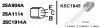
Q1,2 : 2SA1114 = KSA992
Q3,4 : 2SC1117A = KSC1845
Q5,6 : 2SA912 = KSA1220 + heatsinks

Anything else you can think of? The last one I did, I used Nichicon KLs for the low-leakage, ES for the bipolars, and KWs for the rest, and it sounded really sweet.

Thanks for your help,

Lee.
 
with such FEW caps in the audio path, I was thinking of shoehorning in a few more polypropylene stacked film caps in the eq, might make a spectacular difference in sound.
some across the main caps too.
 
Any implications of using stacked film, which are by their nature non-polarized, versus the polarized electrolytics?

Looking at the schematic, I see C1/C2 3.3uF 25v, and C23/24 4.7uF 25v NP that are in the signal path. All the others look to be more bypass caps, either that or their values are getting high. If I'm stacking films, C39 and C40 look like good candidates for when the tone controls are used. Mind you, I never really use them.

Lee.
 
markthefixer said:
do yourself a favor - if you can possibly fit in a stacked film 2.2uf cap for c51 and c52 on the tone amp gwg-123, do it

Those caps are 22uF, not 2.2uF.

Lee.
 
Hooking it up to my test speakers, it seemed to play fine until the power meter was between 1 and 10 watts, at which point the protection relay would click off. I found I could back the volume off slightly, and have the protection relay click off in time with the beat of the music. I tried turning the balance over to the left and then the right channel, it would still do the same thing. I also tried pulling off the source feed from the CD player channels one by one, still the same. It also didn't matter whether the speakers were connected or not.

Still does the same thing even after the recap. I didn't use stacked films for C21 and C22, just KL low leakage, but I didn't with the previous 7800 I worked on, and it wasn't a problem here.

I wish I still had my scope...

Lee.
 
first pull d24 (over current) and see if it stops tripping, then R74, R75 alternately and together to see which channel is tripping it.

you obviously know to look for rising dc offset at the output.

which transistors in the protection circuit are still original?
 
Last edited:
markthefixer said:
first pull d24 (over current) and see if it stops tripping, then R74, R75 alternately and together to see which channel is tripping it.

you obviously know to look for rising dc offset at the output.

Will do that and report back.

markthefixer said:
which transistors in the protection circuit are still original?

None of them. All replaced as per your recommendations.

You know, I bet there's still a bad resistor somewhere. I thought I pulled a leg off each one and checked them, but I might have missed one, there are a lot to check.

Lee.
 
first pull d24 (over current) and see if it stops tripping, then R74, R75 alternately and together to see which channel is tripping it.

you obviously know to look for rising dc offset at the output.

which transistors in the protection circuit are still original?

Pulled D24, and I mean literally. These Pioneer amps with their folded over component leads, you can't just de-solder them and have the component fall out, you have to pull it from the other side.

Anyway, so I pulled D24, and the problem went away. I was able to turn the volume up full, with the power meters pegged at 80w. It only clicked off a few times, which I presumed was the protection circuitry unhappy at the clipping. This was done without any speakers present I might add. D24 tested fine.

Resoldering D24, and pulling R74, the problem came back. Resoldering R74 and pulling R75, same problem. Pulling both of these, still the same problem. Protection relay clicks off in time with the music when the power meters peak up between 1 and 10 watts, or thereabouts.

Lee.
 
D24 conducts signal from Q27 and Q28, (actually one or both of them PULLS current through D24 to ground triggering Q31) either pull them one at a time (or if original, just replace them both) as well as getting rid of original 0.22uf caps.

if it still does it after a double replacement, pull Q27 and Q28 one at a time OR check the resistors connected to their bases. They are the overcurrent sensors and they are triggering on a voltage signal.

a horrible though occurs to me, have you checked the 0.22 ohm emitter resistors? Increased resistance would sensitize the overcurrent threshold.
 
Last edited:
D24 conducts signal from Q27 and Q28, (actually one or both of them PULLS current through D24 to ground triggering Q31) either pull them one at a time (or if original, just replace them both) as well as getting rid of original 0.22uf caps.

if it still does it after a double replacement, pull Q27 and Q28 one at a time OR check the resistors connected to their bases. They are the overcurrent sensors and they are triggering on a voltage signal.

ALL the transistors and electrolytic capacitors on this power amp board are all new. Specifically, Q27 and Q28 were replaced with KSC1845, the 0.22uF caps replaced with Nichicon KLs. Unless the new components are bad, then it would be the resistors.

a horrible though occurs to me, have you checked the 0.22 ohm emitter resistors? Increased resistance would sensitize the overcurrent threshold.

Will check and report back. That's not such a horrible thought, since one channel had blown outputs, it's quite possible the emitter resistors were damaged. I should have thought myself to check them after replacing the outputs. I will kick myself if it turns out to be these.

Lee.
 
Lee; wouldn't be the 1st time someone has forgotten or overlooked parts in a circuit. Don't be so hard on yourself. (You want to borrow my boots?!?) :D

Larry
 
D24 conducts signal from Q27 and Q28, (actually one or both of them PULLS current through D24 to ground triggering Q31) either pull them one at a time (or if original, just replace them both) as well as getting rid of original 0.22uf caps.

if it still does it after a double replacement, pull Q27 and Q28 one at a time OR check the resistors connected to their bases. They are the overcurrent sensors and they are triggering on a voltage signal.

a horrible though occurs to me, have you checked the 0.22 ohm emitter resistors? Increased resistance would sensitize the overcurrent threshold.

I'm still trying to figure out what's going on in this circuit. Pulling D24 stopped the problem, whereas pulling R74 and R75 didn't. I'm guessing these two resistors take the speaker outputs into the protection circuitry, and trip it when a DC output is present. So, what is the purpose of Q27 and Q28? Could I pull the collector leads off each of these to try and figure out which channel is causing the problem?

I'm also assuming the pinouts in the SA-7800 manual are correct for these small signal transistors. The first two groups of transistors show ECB, same as the 992 and 1845 I replaced them with. Nah, it couldn't be a transistor installed wrongly could it?

I wish I'd shotgunned the whole board now, probably would have taken less time. However, I like to try and figure out what's going on, I'm sure with everyone's help I will get there in the end. :music:

Lee.
 
pull Q27 and Q28 one at a time OR check the resistors connected to their bases. They are the overcurrent sensors and they are triggering on a voltage signal.

I provide the answers... :D ahead of time.

yes, you can pull one at a time to pinpoint the channel.
yes r74 and r75 are dc detectors for the channels.


pull Q27 and Q28 one at a time
They are the overcurrent sensors

they are triggering on a voltage signal instead of a current signal

check the resistors connected to their bases

all the way back to the 0.22 ohm emitter resistors


and if one of the 0.22 ohm resistors is elevated in value - minimize the idle current before powering the amp back up after resistor replacement.

dual emitter resistors can be found at mcm electronics.
 
Last edited:
:lmao: a bit louder please, I didn't get that....:no:

Just remember, my posts are usually stuffed chock full of information.

The teacher side of me... (or is it just "show off?")

now, let's figgur oot dis mess....
 
Last edited:
Before repairs :

index.php


After all the transistors had been replaced (before re-cap) :

index.php


Got it yet?


How about a clue?

SA7800-11.jpg

Yes, I had installed Q27 and Q28 the wrong way round. Swapping them around the right way, the amp seems to work fine now, I will keep it under close observation as they say in the medical field. Thanks to all that helped, especially Mark (as always, a great resource).

eeL. (oopss, got that the wrong way too).

Lee.
 
Last edited:
Man... I shoulda warned you about those 1845's. Those reversed lead patterns are tricky when you're doing a ton of replacements on the boards. At least you got it going. Anxious to hear how it goes over some burn-in time.
 
Back
Top Bottom