Hi, so i have this pioneer sa 910 (The japanese version), and it needs a full restoration, and i dont know where to start, anyone help is appreciated.
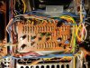
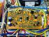
When i firts got it, it turn on but the protection light it stays on and the relay does not click, i recap and change all the transistors on the protection circuit awm 025A, and after that i turn it in on, the protection light when off when the relay click after 2 seconds, after a few mores seconds, the relay clicks off and the protection light come on againg, and is stays like that.
The thing is, that i was trying to take some measures from all the pins on the board, i realice that pin 3 is the only one that has solder in adition to the wire twisting, and while the amp was on, I rub the pin with the miltimeter probe, some sparks come out and the relay click on, and from that moment, when i turn the amp on, the protection light comes on for 2 seconds, then the relay click and the light goes off, and it stays like that.
Did i damage somenthing else? What should i look for?
This are the readings afters the sparks.
Pin 1 -9.8v
Pin 2 -10mv
Pin 3 -30v
Pin 4 grn
Pin 5 -10.5v
Pin 6 -13v
Pin 7 -25v
Pin 8 -27v
Pin 9 7.7v
Pin 10 30v
Pin 11 32v
Pin 12 all over de place
Thanks again for the help.
When i firts got it, it turn on but the protection light it stays on and the relay does not click, i recap and change all the transistors on the protection circuit awm 025A, and after that i turn it in on, the protection light when off when the relay click after 2 seconds, after a few mores seconds, the relay clicks off and the protection light come on againg, and is stays like that.
The thing is, that i was trying to take some measures from all the pins on the board, i realice that pin 3 is the only one that has solder in adition to the wire twisting, and while the amp was on, I rub the pin with the miltimeter probe, some sparks come out and the relay click on, and from that moment, when i turn the amp on, the protection light comes on for 2 seconds, then the relay click and the light goes off, and it stays like that.
Did i damage somenthing else? What should i look for?
This are the readings afters the sparks.
Pin 1 -9.8v
Pin 2 -10mv
Pin 3 -30v
Pin 4 grn
Pin 5 -10.5v
Pin 6 -13v
Pin 7 -25v
Pin 8 -27v
Pin 9 7.7v
Pin 10 30v
Pin 11 32v
Pin 12 all over de place
Thanks again for the help.