

You are using an out of date browser. It may not display this or other websites correctly.
You should upgrade or use an alternative browser.
You should upgrade or use an alternative browser.
Pioneer SA-9100 Problems
- Thread starter zeppoleon
- Start date


Gocasen
New Member
Hey everyone, figured I would bump this thread since it matches my problem and it will be the first fix I put in place. I am handy, and I can do electrical work, but this will be the hardest work I've done. As such, I am trying to make it easy on myself. I've read the following threads:
And also this one. Now, as I gear up to do this, I wanted to make sure I was walking through this properly. My first, of what will hopefully be minimal questions, is around the removal of the boards: do I need to remove the boards entirely, is there an easy way to do this (doubt it), or can work within the amp and just increase my stress levels? It is clear to me that removal is going to make this easier but each additional step can improve failures or items break due to wear on old components.
Is it a correct assumption that I need to take off all of wrapped wires to remove the board?.
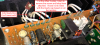
The top piece doesn't concern me, these are few wires and seem straight forward. What made me post was the bottom...
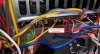
One of the bigger things I was hoping to get help on was the optimal way to either remove the board or work with the boards in the amp. Do I mess with the wires, or do I actually de-pin this thing by removing the sodder where the wires connect (seems even harder than unwiring), or do I go rambo style and cut all the wires, then rewrap em?
I plan to replace the two (four because there are two boards) 2S1451s along with these replacements while in there:
AWH-023 c1 0.22 25 cssa - 0.22 50 667-ECQ-V1H224JL3
AWH-023 c2 0.47 25 cssa - 0.47 50 667-ECQ-V1H474JL3
AWH-023 c3 33 16 cea - 33 25 647-UPW1E330MDD
AWH-023 c6 33 16 cea - 33 25 647-UPW1E330MDD
AWH-023 c12 470 6 cea - 470 6.3 647-UPW0J471MPD
Thanks in advance! Also, I don't know terminology well, so bear with me.
- https://audiokarma.org/forums/index...on-recently-purchased-pioneer-sa-9100.344695/
- https://www.audiokarma.org/forums/i...sues-no-sound-blowing-fuses-etc.331932/page-5
And also this one. Now, as I gear up to do this, I wanted to make sure I was walking through this properly. My first, of what will hopefully be minimal questions, is around the removal of the boards: do I need to remove the boards entirely, is there an easy way to do this (doubt it), or can work within the amp and just increase my stress levels? It is clear to me that removal is going to make this easier but each additional step can improve failures or items break due to wear on old components.
Is it a correct assumption that I need to take off all of wrapped wires to remove the board?.
The top piece doesn't concern me, these are few wires and seem straight forward. What made me post was the bottom...
One of the bigger things I was hoping to get help on was the optimal way to either remove the board or work with the boards in the amp. Do I mess with the wires, or do I actually de-pin this thing by removing the sodder where the wires connect (seems even harder than unwiring), or do I go rambo style and cut all the wires, then rewrap em?
I plan to replace the two (four because there are two boards) 2S1451s along with these replacements while in there:
AWH-023 c1 0.22 25 cssa - 0.22 50 667-ECQ-V1H224JL3
AWH-023 c2 0.47 25 cssa - 0.47 50 667-ECQ-V1H474JL3
AWH-023 c3 33 16 cea - 33 25 647-UPW1E330MDD
AWH-023 c6 33 16 cea - 33 25 647-UPW1E330MDD
AWH-023 c12 470 6 cea - 470 6.3 647-UPW0J471MPD
Thanks in advance! Also, I don't know terminology well, so bear with me.
Attachments
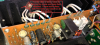
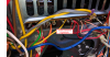

The pins have TWO prongs in the board, they will NOT come out gracefully - even after a good desoldering, because they are crimped in together long before any soldering.
Do NOT unwrap - don't figure on getting the correct wires and tools to rewrap.
The brown thing screwed to the heat sink is the "nasty one" not to mess with. Those white wires LOVE to break off flush at the case.
The transistor sockets can be freed up from the heat sink, and later carefully reinstalled. That gives more freedom of motion, AND the output transistors should be regreased.
Other transistors bear replacement.
Be explicitly able to rematch actual transistors to the socket each came from.
Do NOT unwrap - don't figure on getting the correct wires and tools to rewrap.
The brown thing screwed to the heat sink is the "nasty one" not to mess with. Those white wires LOVE to break off flush at the case.
The transistor sockets can be freed up from the heat sink, and later carefully reinstalled. That gives more freedom of motion, AND the output transistors should be regreased.
Other transistors bear replacement.
Be explicitly able to rematch actual transistors to the socket each came from.

moodydan
I love the punk rock.
Once you've removed the heatsinks from the amps, as suggested above, I think you'll find you do have ample space to work. Be careful about moving and twisting the boards too much though, as you can break the wires at their wraps which causes many headaches (ask me how I know...on the 9100 I just finished up...). The only board(s) that I find to be terribly really tight for space on the 9100 are the phono boards. Luckily, someone had been in mine before and made a bit of a mess disconnecting wires, so while I was cleaning up that "work" I was able to have almost full access to those. Good luck, these guys will take care of you if you're patient and follow instructions as you go!
Gocasen
New Member
So replacements have been going swimmingly (minus my soldering iron breaking immediately), took a few detours, and while button up the bottom, I decided to replace the capacitors in the protection circuit since I already had it off. Along the way, I noticed a clear "goop" on the filter board but from reading other posts it looks like brown sludge is the problem. As such, the clear goop below is fine and normal, is that a correct statement?


gslikker
Super Member
Above is glue. The black things are coils, nothing to worry. If any ferrite inside, they are heavy for their size.so leave the glue.
Sidenote, those blue Sanyo capacitors are solid aluminium ones and they probably leak (electrically). If really bad they influence the circuit.
Sidenote, those blue Sanyo capacitors are solid aluminium ones and they probably leak (electrically). If really bad they influence the circuit.
Gocasen
New Member
Gslikker, thanks for the heads up, I have a bunch of caps for each board since I bought a replacement set before I found the website.
Once, I finished replacing caps, and to make sure my original problem was resolved, I decided to button up the 9100 and went to see if the replacements resolved my issues. The first moment I turned it on, it followed the normal progression, protection circuit flips on, then turns off, nothing crackling through the speakers, and so I turned on an album. Halfway through a song, the protection circuit triggered, but static came through (normally it cuts it completely). I turned it off immediately.
I wanted to see if it was a fluke, but I knew I would only get one opportunity to document the specifics, so I took video as I turned it back on with nothing playing. It was at that moment that the static and pops came through while the protection circuit was engaged and continued after the protection circuit disengaged. This was newer, in the past it would be a bit before this type of behavior happened (maybe 20 minutes or so) now it is happening the moment it turns on.
I replaced the following caps:


Once, I finished replacing caps, and to make sure my original problem was resolved, I decided to button up the 9100 and went to see if the replacements resolved my issues. The first moment I turned it on, it followed the normal progression, protection circuit flips on, then turns off, nothing crackling through the speakers, and so I turned on an album. Halfway through a song, the protection circuit triggered, but static came through (normally it cuts it completely). I turned it off immediately.
I wanted to see if it was a fluke, but I knew I would only get one opportunity to document the specifics, so I took video as I turned it back on with nothing playing. It was at that moment that the static and pops came through while the protection circuit was engaged and continued after the protection circuit disengaged. This was newer, in the past it would be a bit before this type of behavior happened (maybe 20 minutes or so) now it is happening the moment it turns on.
I replaced the following caps:
- The two large filter caps: ACH-020-0 15,000uF/50V
- On the Power Amp Assembly:
- AWH-023 c1 0.22 25 cssa - 0.22 50 667-ECQ-V1H224JL3
- AWH-023 c2 0.47 25 cssa - 0.47 50 667-ECQ-V1H474JL3
- AWH-023 c3 33 16 cea - 33 25 647-UPW1E330MDD
- AWH-023 c6 33 16 cea - 33 25 647-UPW1E330MDD
- AWH-023 c12 470 6 cea - 470 6.3 647-UPW0J471MPD
- And Q6 and Q7 2SC1451 with the recommended replacement here
- On the Protection Circuit (Previous work was done by the local shop on this circuit, looks like they replaced some, you can see the soldering job from them)
- AWM-025 c1 0.22 10 cssa - 0.22 50 667-ECQ-V1H224JL3
- AWM-025 c2 0.22 10 cssa - 0.22 50 667-ECQ-V1H224JL3
- AWM-025 c3 cea 330 6 cea - 330 6.3 647-UPW0J331MED
- AWM-025 c4 cea 330 6 cea - 330 6.3 647-UPW0J331MED