• The move to the new server is done. There are some software and database maintenance updates in process. This has us passing the hat around to help out. We appreciate any donations. Seriously, even a dollar helps. The payment page may be found here - https://www.audiokarma.org/support.html

Pioneer SA-9900 issues

grgmchl

Member
Hello,

I recently got my hands on a Pioneer SA-9900 amplifier. I'm not exactly sure what's wrong with it but so far I have determined that one channel has zero output, no hum while the other channel sounds clean but not as loud as it should.

I've hooked it up as following:

Pioneer TX-9500 tuner -> RCA cable -> Tuner Input; I definitely hear static noise and some radio channels. The reception quality is decent especially given that is has no antenna;

MacBook Pro laptop -> 3.5mm jack <=> RCA Cable -> AUX 1 Input; I can play music in iTunes or YouTube and I get sound in one channel, the 2nd channel is completely silent. I adjusted the balance knob accordingly, no change. The speaker selection dial is set to A and the speakers are connected to the A section. I did not try the B outputs.

At this point I'm thinking about bringing it to a shop for a complete diagnostic. I also have a cheap multi-meter lying around. Is there anything else I could do to further troubleshoot this?
 
Register to hide this ad
I think this project is too complicated for my skill level. If you guys know someone in the Montreal area who's knowledgeable enough to work on it let me know.
 
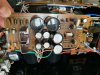
I decided to accept the challenge and fix it myself. I've disassembled most of if according to the official service manual. This SA-9900 is full of dust - I would like to know what would be the best product/spray/chemical to clean the PCBs, the chassis, front plate, knobs etc. Thanks!
 
I have disassembled most of my sa-9900 so far on a wooden workbench. Upon removing the front aluminum faceplate, I checked the volume potentiometer - whenever I turn it with my fingers it makes a click. This was not the case when the device was fully assembled, in other words the volume potentiometer had a smooth movement, no clicking. Can anyone tell me what's the correct behaviour, smooth/clicking?
 
You need to build a dim bulb tester.
Don't go taking the whole thing apart either, not just yet.
Buy deoxit d5 and faderlube and clean all pots and switches first, you might get lucky and everything's just dirty.

Do you have temp controlled soldering Station?
Service manual?

Lots of things can go wrong when working on these, trust me I know from making my own mistakes, slow down and start reading up on all of the threads on these units before proceeding further.

Welcome to audiokarma, your in the right place. Hopefully other members will provide you with proper guidance!
 
Thanks for the reply PTL-Pioneer.

Regarding the DBT: The amp turns on fine, the filter caps (22,000uF/63V) are in good shape, I measured all voltage rails across AWS-069, AWX-083, AWR-070, AWR-077, AWR-037 & AWR-038. The relays are functional as well.

This SA-9900 is very dusty and dirty inside, it was unused sitting in storage for a long time hence the reason for disassembling and cleaning it. The pots for bass/treble/$function will be cleaned with deoxit - Currently waiting for it to be delivered.

I have all the necessary documentation for this amp

My question still stands: What kind of behavior does the volume control have? Is it smooth or does it click?
 
No idea to be honest, not familiar with that unit, some have detent, clicky, while others have no detents. If yours is clicking when you turn it I can only assume its detented.

Other folks will know from first hand experience, I'll let them chime in
 
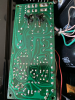
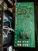
I'm continuing to work on this SA-9900. Upon disassembling the unit for general cleaning, I noticed that board "AWR-070-A", Power Supply Circuit Assembly PCB has been serviced and has two transistors soldered on the foil side (copper side):

- A628A 25D
- C869 41C

As you can see, some copper traces on the foil side have been mechanically/physically interrupted.

I'm attaching pictures for further clarification - If a higher resolution is needed let me know.IMG_5855PNG.png IMG_5856PNG.png IMG_5854PNG.png

Any ideas?
 
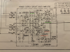
Looking at the schematics (attached, AWR-070-A, revision A I guess) and looking both at the foil and component side:

- I believe this was done at the factory since there is no place on the component side for Q9 (2SC869) and Q10 (2SA628A)
- I'm surprised to see such a sloppy job, the solder joints were clearly done by hand;
- All transistors exept Q1 (2SD313P) and Q2 (2SB507P) have oxidized, backened leads. After reading other threads on AK, members suggested replacing these since they can become problematic.
- I will measure again the voltages across all power rails.
 

Attachments

  • IMG_5862 copy.png
    IMG_5862 copy.png
    719.4 KB · Views: 19
What probably happened is that the Q1 and Q2 power pass regulator transistors required more drive than Q3 & Q4 were able to drive, so they changed them over to higher gain Darlingtons by adding Q9 & Q10..
They probably already had a bunch of PC boards, so they had to retrofit Q9 & Q10 onto them, and the cleanest production way was on the bottom.

I call attention to the service manual fragment:
upload_2021-4-23_23-4-43.png

We don't see this much in Pioneer equipment...

First step in testing is to throw the normal /separated switch to separated, and take two rca cables and plug them:
one from pre-out LEFT to power amp RIGHT
the other pre-out RIGHT to power amp LEFT
and see if the dead channel stays put (power amp problem)
or if the dead channel MOVES to the other channel (preamp problem)
 
Last edited:
Hello grgmchl,

I used to have a SA-9900 back in the 80s, bought it at a discount for Hfl 800,- (app $ 400) when the official price was Hfl 2.000,-. The serial# was WB9100886M.
I had trouble with it, so I gave it away. Regret it a bit now. I definitely can remember that the volume control had a 'clicking' character. I found it nice to the touch.
 
Last edited:
Hi Mark,

I performed the steps you mentioned in your last post. All steps below have been performed with the speakers settings set to "Speakers A" and two speakers connected to Speakers A, Right + Left (photo attached);

1. NORMAL/SEPARATED switch was switched to the SEPARATED position;

2. Took a male-male RCA patch cable and connected it as following:

- PRE-OUT Left Channel => POWER IN Right Channel;
- PRE-OUT Right Channel => POWER IN Left Channel;​

I'm adding a photo just to make sure we're on the same page;

Conclusions:

1. The current working channel after instructions in point 2. HAS MOVED to Right, Speakers A;

2. The DEAD channel went Left. This was previously working - Speakers A;

3. The BALANCE dial all the way to the right no sound;

3a. The BALANCE dial all the way to the left I get sound in the RIGHT channel; Prior to this setup balance was still inverted. Will test again without this setup.

3. The MODE Dial has the following settings: REV, STEREO, L+R, L, R - None of these settings make a difference. Sound plays in Speakers A, Right channel.

Based on your statement I guess there's a problem in the preamp stage?

Let me know if I can provide further information/troubleshooting.
 
Hello grgmchl,

I used to have a SA-9900 back in the 80s, bought it at a discount for Hfl 800,- (app $ 400) when the official price was Hfl 2.000,-. The serial# was WB9100886M.
I had trouble with it, so I gave it away. Regret it a bit now. I definitely can remember that the volume control had a 'clicking' character. I found it nice to the touch.

Hi, thanks for the answer. Something is strange - While the amplifier's face plate was assembled, along with the underlying foam tape designed to concentrate the light from the two lamps on the volume scale, the volume attenuator (volume pot) had a smooth movement while now it clicks as you describe. It works well, no clicks, noise or otherwise malfunctions. I've tried re-attaching the plate and the volume knob, same behaviour, clicky movement.

I'm continuing to troubleshoot this amp by looking at the preamp schematics and reading some of the forum posts. BTW, the Control AMP Assembly AWG-031 & AWS-080 are a pain to work on due to the way they're installed in the chassis :(

Thank you guys!
 
back to my SA-9900 restoration thread, I have a question about the AWX-083 board, details below;

The first picture I'm attaching comes from the hard paper schematic for my SA-9900. Post / Pin position 7, respectively 8 mention a ceramic capacitor C4 0.01uF that is physically missing from the PCB. I can confirm it is not present on the foil side and the solder holes are covered with solder.

If I am to replace this part, what voltage should it be? There are a couple of 0.01uF in the power supply circuitry used as safety capacitors.

Is this something I should worry about?
View media item 25404View media item 25403
 
Found the answer to my question - C4 0.01uF ceramic 150V/DC 1.4kV is mounted on a separate ceramic socket on the chassis. It is then linked to AWX-083 pins 7, 8 using two jumper wires.
 
I would like to know if the TO-3 capsules on the output transistors are supposed to leak current. I touched one by mistake while the amp was functioning and I got electrocuted. I cna confirm that the radiator is fine and does not show any leakage. The output transistors are pasted and isolated with mica wafers.

I just used my multimeter on the DC Voltage setting and I can measure anywhere between 58.00vdc to 60.00vdc on the TO-3 capsules. The measurement is not constant, sometimes I get 0.550vdc to 0.850vdc.
 
Last edited:
The cases on the TO-3 package are directly connected to the collector of the transistor, they are not leaking, they are electrically hot! That is why there is an electrical insulator between the transistor and the heatsink. Plus or Minus 58vdc is the power supply voltage for the power amp output transistors. That is enough to give you a tingle (or kill you upload_2021-7-10_17-6-18.gif), especially if you get across the +58vdc to the -58vdc collectors. Be careful!
 
I finally have some time at my disposition to work on the SA-9900. I need help choosing parts for the power supply section of this amp, see below.

Sections below refer to the service manual, KCU version (North American SA-9900)

10.2 ELECTRO-PARTS

C1 - 22,000uF / 63v -> Nichion LKG1K223MKZF
C2 - 22,000uF / 63v -> Nichion LKG1K223MKZF

C3 - 0.01uF / 250VAC -> DE2F3KY103MA3BM02F (ACG-001-0, see note #1)
C4 - 0.01uF / 150VAC / 1.4kV DC -> ??? (ACG-003-0, see note #2)

C5 - 0.0047 / 50V -> See note #3
C6 - 0.0027 / 50V -> See note #3

10.8 - POWER SUPPLY CIRCUIT ASSEMBLY-1 (AWR-069-A)

C1,C2,C3,C4 - Ceramic Capacitor 0.01uF / 150V, see note #4 (Part # ACG-004-0)

10.9 POWER SUPPLY CIRCUIT ASSEMBLY-2 (AWR-070-A)

C1,C2,C3,C4 - Ceramic Capacitor 0.01uF / 150V see note #4 (Part # ACG-004-0)

================================================================

Note 1: Murata Part No. DE2F3KY103MA3BM02F seems to fit the bill in terms of specs.

Note 2: These snubber capacitors are no longer manufactured. I cannot find any parts with identical specifications. Some forum users mentioned using CDE quencharcs, however they don't seem to be available in 0.01uF.

Note 3: There are polyester/mylar green resin coated caps used for the microphone input. Can I replace them with WIMA film capacitors, same spec? The three components in question (two C5,C6,R3,R4) are damaged / have residue on them. I believe the residue comes from the paper tape used for wrapping/protecting them.

Note 4: I'm unable to find multilayer ceramic capacitors with these specifications (0.01uF rated 150VDC). Can someone suggest a replacement?
 
Back
Top Bottom