• The move to the new server is done. There are some software and database maintenance updates in process. This has us passing the hat around to help out. We appreciate any donations. Seriously, even a dollar helps. The payment page may be found here - https://www.audiokarma.org/support.html

Pioneer Spec-1: Novice Seeks Repair Help

Soup Wins

New Member
Hello people of Audio Karma,
I am new here and looking for some help. Hopefully this is the correct place to post this.
I have been trying to teach myself about vintage stereo repair, and have had some good success refurbishing speakers, replacing burnt out lamps in receivers, and other simple tasks. I've had good fun, and made a little money cleaning up and selling systems locally.
I have now run into a technical repair with a Pioneer Spec-1 Preamplifier that is beyond my skills to fix so I was hoping someone on here might be patient enough to walk me through the diagnosis and repair of this old gear.

The problem is that no signal is making if from any of the inputs to the output section. (Yes, I am aware that it is not an amplifier, and have hooked it up correctly). I have downloaded the service manual for this unit, but am not super confident in reading it. Opening up the bottom panel I found fuses numbers 2 and 3 were expended. I replaced them and they burned out again instantly on startup. I was able to deduce that those fuses are connected to the power supply board, AWR-094A.
I would appreciate any help and guidance on what to do next. The power supply board looks fine, no obvious damage, so how do I go about diagnosing the problem? Please bear in mind that I don't know a whole lot about electronics, so please use layman's terms if possible.
Thank you to anyone who reads this.

~Benjamin
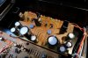
Here are some pictures of the unit and power supply board.
DSCF1860.JPGDSCF1862.JPGDSCF1861.JPG
 
Register to hide this ad
Someone else suggested I check the voltage between the pins (1-16) on the AWR-094A board and the chassis. I got these voltages:
pins 1 thru 5 and 8 thru 12 are showing -.15v
Pin 6 is -.17v
Pin 7 is -.02
Pin 13 is +36v
Pin 14 and 15 are +26v
 
If you're going to try this, build a dim-bulb tester before you do anything else. I wouldn't suggest this as a noob project, tbh. At minimum I would suggest rebuilding the power supply in it's entirety. After that, there are a bunch of known sketchy transistors in these iirc.
 
pins 1 thru 5 and 8 thru 12 are showing -.15v
Pin 6 is -.17v
Pin 7 is -.02
With fuses 2 & 3 blown, there will be garbage (0V?) on these pins

If you're going to try this, build a dim-bulb tester before you do anything else. I wouldn't suggest this as a noob project, tbh. At minimum I would suggest rebuilding the power supply in it's entirety. After that, there are a bunch of known sketchy transistors in these iirc.
Very good advice
 
The above. No offense.

But if you insist on working on it, build a DBT, and start checking for shorted transistors and diodes with a DMM.
 
Definitely DBT and I'll go with the rest of the fellas above and recommend you cut your teeth on one or two units with less value. It's not uncommon for people starting out to make a bit of a mess between the start of the project and the end, with some fried components and lifted traces amongst other issues. It would be much better off to work through those gotchas with a $50 receiver or amplifier.
 
I can join with the group above. That is a pretty valuable (Expensive) unit to start with. To work on something like that you should have a good knowledge of electronics, and troubleshooting down to component level. If you do the wrong thing you can fry the transformer or create more problems than you have now.
With those 2 fuses blowing, it means the secondary side of the power transformer see a short.
The short could be bad rectifiers on the fuse board, shorted filters, shorted Regulator transistors, shorted caps on any of the boards, because the +48v and -48 volts regulated supply seems to feed all the boards. First thing is to pull the power cord as ohms checks are done with power disconnected. The way I troubleshoot things like this is to use an old fashioned analog multimeter (OHMS X1 scale) and look to find where there is a short to chassis ground. Can the short be found at the rectifiers? At the primary filters? If not then I look at the regulators and output pins for the +48v and -48 volt supplies. When a short if found (for example at the output pins, the wires on those pins need to be unsoldered to identify if the short is on the regulator board, or on one of the wires feeding the other boards.

And after the shorted component is found, and replaced and you get it to power up, first via dim bulb, there are other items the SPEC usually need addressing. Cleaning all controls and switches with the proper chemicals, removing the cover on the big speaker relays and cleaning/polishing the contacts etc.

My suggestion is to find a local vintage Audio Tech, probably in his 60's, who has a lot of experience and can get it fixed pretty quick. Shorts are not a hard problem to diagnose and fix if you have the experience. That an $800 preamp you have. If you fry the transformer, it will be real hard and very expensive to find another, if not impossible.
 
I want to thank you all for the honest input. I guess I am outgunned on this one. I don't want to mess it up so I guess I will not go mucking around in there. I can sense very real hesitation coming from you all to start telling an amateur where to go sticking his soldering iron in a nice old piece of gear such as this. I will humble myself and not take a dive into the deep end to start.
There is one shop in my town that I am told fixes vintage equipment but I imagine it will be very pricey (Santa Cruz, CA). Is there someone on the West Coast that offers reasonably priced repair work on this sort of thing? I'm very good at/comfortable with shipping stuff, so I assume that would be the reasonable best way to get it professionally serviced.
Thank you all again, I look forward to future assistance from the community!
 
Back
Top Bottom