• The move to the new server is done. There are some software and database maintenance updates in process. This has us passing the hat around to help out. We appreciate any donations. Seriously, even a dollar helps. The payment page may be found here - https://www.audiokarma.org/support.html

Pioneer Spec 4 Recap

CohibaJoe

AK Subscriber
Subscriber
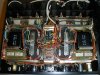
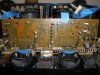
Yes...another one. With the Spec 1 completed....Picked up a Very Nice Spec 4 that was in the closet for 20+ years (low use).

Going to use "mattsd" Spec 4 thread as what I also used for his Spec 1 thread...:yes:

Some thread "markthefixer" used United Chemi-Con. I have used (ADCOM) SX-1250, 1050. I will pick-up both to compare.

Main Caps: United Chemi-Con 22000uf 100v and ADCOM 22000uf 100v
Lamps: LEDS
Caps: "mattsd" thread http://www.audiokarma.org/forums/showthread.php?t=449270

Order going in tonight. Till then.....
 

Attachments

  • PioneerSpec4a.jpg
    PioneerSpec4a.jpg
    42 KB · Views: 90
  • PioneerSpec4b.jpg
    PioneerSpec4b.jpg
    90.4 KB · Views: 128
  • PioneerSpec4c.jpg
    PioneerSpec4c.jpg
    119.2 KB · Views: 119
Register to hide this ad
Good luck Joe. Be careful, and don't hurry or get frustrated.

What are you going to use for meter lamps? There are some interesting warm white LED fuselamps out there I have been curious to try on my pair of SPEC-4s.

Both of my SPEC-4s were boat anchors when I started restoring them. They are beastly workhorses now, for several years after restoration.

Good luck,
Rich P
 
Good luck Joe. Be careful, and don't hurry or get frustrated.

What are you going to use for meter lamps? There are some interesting warm white LED fuselamps out there I have been curious to try on my pair of SPEC-4s.

Both of my SPEC-4s were boat anchors when I started restoring them. They are beastly workhorses now, for several years after restoration.

Good luck,
Rich P
Will be going Slow on this 1. Picked up a set of Blue and Warm White from FleeBay...Guy local to me makes these...Used a set for Onkyo M-504 that is Very Nice.
 
On the Amp Board.....

?....Replacing all the Transistors so will I need to Adjust the Power Limiter?
 
Have not needed one(maybe time to buy 1)....Looks like a trip to a Local tech.
IF you know what you are seeing, it might be possible to understand when the limiter kicks in, using a meter. I would want to do that with a scope to correlate to meter response. Then you might get a way with just the meter, later on. Not overly recommended, but do-able.

Enjoy,
Rich P
 
IIRC, from what i have read in the sm, but actually have never done it,
you are to set the AC sine wave level as stated, amp connected into a 8 ohm dummy load. While measuring thd, set the pot on the top half AC cycle, for the thd number IIRC 0.1%, then using a scope to set the second pot on the lower half AC cycle, so that the I limiter cuts in/clips symmetrically. I do not think there would be any other way of doing it.
 
Last edited:
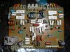
Power Amp Boards

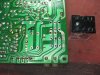
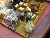
Relay replaced with:

MY2-02-DC48

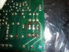
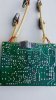
Picture 3 back side of board. Needed to drill 3 holes.

Now when the board goes back into unit...this is going to JUST fit hight wise.
 

Attachments

  • PioneerSpec4d.jpg
    PioneerSpec4d.jpg
    106.2 KB · Views: 119
  • PioneerSpec4e.jpg
    PioneerSpec4e.jpg
    109.2 KB · Views: 114
  • PioneerSpec4f.jpg
    PioneerSpec4f.jpg
    98.6 KB · Views: 114
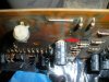
Meter Amp Board

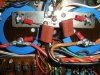
Once Cap has Vented :yikes:...And why do I Recap my Gear..:yes:
 

Attachments

  • PioneerSpec4h.jpg
    PioneerSpec4h.jpg
    84.2 KB · Views: 110
  • PioneerSpec4g.jpg
    PioneerSpec4g.jpg
    100.1 KB · Views: 106
  • PioneerSpec4i.jpg
    PioneerSpec4i.jpg
    101.2 KB · Views: 102
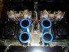
Main Caps and Relays:

United Chemi-Con 22000uf 100v
Omron LY2F-AC110/120

The Old Relay Covers do fit..A-bit snug by the Clips.
 

Attachments

  • PioneerSpec4j.jpg
    PioneerSpec4j.jpg
    91.4 KB · Views: 91
At this time....DONE

Using Blue LEDS.

Going to let this burn on 100hrs....Then I will replace the United Chemi-Con with ADCOM just to see
if there are any Sound differences.
 

Attachments

  • PioneerSpec4k.jpg
    PioneerSpec4k.jpg
    57.8 KB · Views: 61
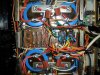
Going over some threads...."markthefixer" suggested adding Stack Films for a Smoother Sound.

I can say a Big :yes:
 

Attachments

  • PioneerSpec4s.jpg
    PioneerSpec4s.jpg
    109.9 KB · Views: 113
  • PioneerSpec4t.jpg
    PioneerSpec4t.jpg
    127.7 KB · Views: 110
20170202_123411.jpg 20170202_123426.jpg 20170202_123429.jpg
Power Amp Boards

Relay replaced with:

MY2-02-DC48

Picture 3 back side of board. Needed to drill 3 holes.

Now when the board goes back into unit...this is going to JUST fit hight wise.

Hey Joe, I used the same relay that you used here on the output board of my amp and I wanted to ask if you did more work than that shown in your above images. I did not have good luck going mine. I clipped off the two leads from the relay on the end nearest the outside with the contact points and as far as I can tell by your images soldered it back in just as you did. I brought it back up on the DBT/Veriac with no indications of a short then set the DC offset. After that I checked bias and it was off started slowly adjusting it and and got a little smoke party..
 
I don't see how either of you managed to squeeze the driver board into place with the relay in the lower position (CohibaJoe, missed this thread when you posted it back in 2015).

Here's my install of the Omron MY2 on the Spec 4 (thread here):
index.php


Relay in the top position, for a variety of reasons.
 
Her
I don't see how either of you managed to squeeze the driver board into place with the relay in the lower position (CohibaJoe, missed this thread when you posted it back in 2015).

Here's my install of the Omron MY2 on the Spec 4 (thread here):
index.php


Relay in the top position, for a variety of reasons.

Excellent workmanship EW...
Here's a board-prep view following your design.
Amp Board Drilled and Prepped for Omron MY2.jpg

Fits perfect. Clears the chassis by less than 1/8". Thanks for the guidance.
 
View attachment 862011 View attachment 862012 View attachment 862010

Hey Joe, I used the same relay that you used here on the output board of my amp and I wanted to ask if you did more work than that shown in your above images. I did not have good luck going mine. I clipped off the two leads from the relay on the end nearest the outside with the contact points and as far as I can tell by your images soldered it back in just as you did. I brought it back up on the DBT/Veriac with no indications of a short then set the DC offset. After that I checked bias and it was off started slowly adjusting it and and got a little smoke party..

Did you replace the bias pots? If not, I'm wondering if a dead spot on the 40 year old pot caused release of the magic smoke...
 
Back
Top Bottom