• The move to the new server is done. There are some software and database maintenance updates in process. This has us passing the hat around to help out. We appreciate any donations. Seriously, even a dollar helps. The payment page may be found here - https://www.audiokarma.org/support.html

Pioneer Spec4

Testadmin

New Member
Hello, before I get to my problem I would like to say thank you to everyone for the absolutely valuable information posted here in this forum.
I was able to fix a few great and old devices because of you experts. T H A N K Y O U !!!!!
This is my first thread. (I'm from Germany so please excuse my poor English)
Here is my problem:
About a year ago I bought both Pioneer Spec1 and Spec4 devices.
When I bought both the previous owner said everything was fine and working. Then I tested both devices on pretty bad speakers. They worked. I had very little time due to my job, so the two devices were put in a corner. About a month ago i pulled them both out and looked at the inside.
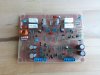
I saw that the Spec4 had completely different amplifier boards installed. They were attached with hot glue and silicone. Great!!!
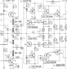
After I've calmed down i downloaded the service manual and looked at the amplifier circuit board. I drew the layout and asked a company to make the two circuit boards for me.
A week later I received the brand new boards. I wasted no time I immediately started to assemble the circuit boards. A few days later the first problem occured. The coils with 1.1 uF. I looked online at some pictures of the circuit boards and also compared the coils with other devices from Pioneer. I found out that the SX-1980 has the same ones. i looked at the number of turns, thicknes of the wire and and tried to replicate it as good as possible. Problem solved.
After a few more problems that arose, now only one thing remains. The thermistor TH101-2.
I searched online and of course in this forum. Unfortunately without success. I would like to know what value this part has. I would love to get the circuit boards done and finally enjoy the sound of these two devices.
Oh yes, one more thing. Are there errors in the service manual that I should definitely pay attention to?

Thank you in advance.
 
Register to hide this ad
Sounds like you've made great progress so far. But could you possibly share some pictures of the amp boards that were glued in? Maybe we can identify if they are original or not? Have you salvaged the STV-3H didoes from the old boards if they are the original boards? They're rare and important. I'm impressed that a company remade the board for you from a drawing. Have you modified the board to take modern relay sizes? The original size of relay used on the amplifier boards of the SPEC-4 is quite small and NLA as far as I am aware.
 
Sounds like you've made great progress so far. But could you possibly share some pictures of the amp boards that were glued in? Maybe we can identify if they are original or not? Have you salvaged the STV-3H didoes from the old boards if they are the original boards? They're rare and important. I'm impressed that a company remade the board for you from a drawing. Have you modified the board to take modern relay sizes? The original size of relay used on the amplifier boards of the SPEC-4 is quite small and NLA as far as I am aware.
I would like the contact info of the board maker for personal reference. In fact, I have a broken power supply board for a Pioneer Spec 2 that I need a replacement for right now.
 
They are part of the power limiter circuit. I would surmise they are reducing sensitivity as their temperature increases,
which makes sense as the power limiter transistor Q13 would become more sensitive (Lower Vbe) as it warmed up.

I read 92 ohms on one, 104 ohms on another at 26 degrees c.

28 deg c 96 ohms in free air
53 deg c 54 ohms in plastic bag in hot water bath

53 - 28 = 25 degrees
96 - 53 = 43 ohms.
with a 100 ohm pot paralleled with a 330 ohm resistor it's basically 75 ohms in series on a one to 3 volt circuit.
self heating should be low.

I would take a chance on 527-2003-100 the RL2003-62.4-73-D1 from mouser.com.

This selection is based on the 100 ohm approximate value, coupled with the physical size (resistance to self heating) and available thermistors. The resistance value was the dominating consideration in the catalog, as many many resistance values are available, but once that resistance is chosen (and for us the choice is already made), there aren't any others at the same resistance to choose between. That means that data on resistance drop as the temperature rose wasn't selectable.


upload_2022-7-14_20-41-11.png
 
Last edited:
You guys need to read the post a bit more critically:
After I've calmed down i downloaded the service manual and looked at the amplifier circuit board. I drew the layout and asked a company to make the two circuit boards for me.

no different in concept than the other Printed Circuit Boards we've done and farmed out ourselves....
 
Sounds like you've made great progress so far. But could you possibly share some pictures of the amp boards that were glued in? Maybe we can identify if they are original or not? Have you salvaged the STV-3H didoes from the old boards if they are the original boards? They're rare and important. I'm impressed that a company remade the board for you from a drawing. Have you modified the board to take modern relay sizes? The original size of relay used on the amplifier boards of the SPEC-4 is quite small and NLA as far as I am aware.

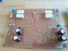
Hi, these boards are definitely not original. Unfortunately they don't have STV-3H diodes either.
However, I read in this forum that the STV-3H can be replaced.
 

Attachments

  • IMG_20220715_072048_590.jpg
    IMG_20220715_072048_590.jpg
    121.6 KB · Views: 66
  • IMG_20220715_072054_268.jpg
    IMG_20220715_072054_268.jpg
    107.9 KB · Views: 65
They are part of the power limiter circuit. I would surmise they are reducing sensitivity as their temperature increases,
which makes sense as the power limiter transistor Q13 would become more sensitive (Lower Vbe) as it warmed up.

I read 92 ohms on one, 104 ohms on another at 26 degrees c.

28 deg c 96 ohms in free air
53 deg c 54 ohms in plastic bag in hot water bath

53 - 28 = 25 degrees
96 - 53 = 43 ohms.
with a 100 ohm pot paralleled with a 330 ohm resistor it's basically 75 ohms in series on a one to 3 volt circuit.
self heating should be low.

I would take a chance on 527-2003-100 the RL2003-62.4-73-D1 from mouser.com.

This selection is based on the 100 ohm approximate value, coupled with the physical size (resistance to self heating) and available thermistors. The resistance value was the dominating consideration in the catalog, as many many resistance values are available, but once that resistance is chosen (and for us the choice is already made), there aren't any others at the same resistance to choose between. That means that data on resistance drop as the temperature rose wasn't selectable.


View attachment 2616016

Hi, thank you for the detailed information and the link to mouser. I'll place an order and install the components. This definitely gets me going. Thanks a lot.
 
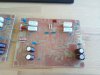
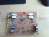
One component after the other. And everything times two
 

Attachments

  • IMG_20220623_101707_343.jpg
    IMG_20220623_101707_343.jpg
    116.1 KB · Views: 48
  • IMG_20220623_144146_530.jpg
    IMG_20220623_144146_530.jpg
    125 KB · Views: 50
  • IMG_20220715_072113_141.jpg
    IMG_20220715_072113_141.jpg
    134.6 KB · Views: 56
I would like the contact info of the board maker for personal reference. In fact, I have a broken power supply board for a Pioneer Spec 2 that I need a replacement for right now.
I have thought about remaking the SPEC-4 boards for a while but had no need to do it. Though Having them made on a better quality materials available today would be nice - together with the modification for the MY2 relays. I could look into making this and possibly the SPEC-2 power board too.

Great job on remaking the SPEC-4 board @Testadmin - it looks great. Those boards you pulled out look to be really generic amplifier boards from a magazine or something. That's a real shame but you've got most of what you need. Were the original heatsinks still there? Is anything else missing?

There are some STV-3H's for sale on "the bay" from a German seller I believe. I've bought a couple myself and they look to be genuine and do work perfectly in my experience so that should be an easy one. You can put together a diy STV-3H, but if the original is available, I'd elect for that for a neater job.

The STV-4H's though... I think they are all but gone so might have to go with the DIY version of that. The only other option which might be a bit more future proof, is to redesign the bias circuit to utilise a transistor rather than a biasing diode. But I'm not sure if this is feasible.
 
I have thought about remaking the SPEC-4 boards for a while but had no need to do it. Though Having them made on a better quality materials available today would be nice - together with the modification for the MY2 relays. I could look into making this and possibly the SPEC-2 power board too.

Great job on remaking the SPEC-4 board @Testadmin - it looks great. Those boards you pulled out look to be really generic amplifier boards from a magazine or something. That's a real shame but you've got most of what you need. Were the original heatsinks still there? Is anything else missing?

There are some STV-3H's for sale on "the bay" from a German seller I believe. I've bought a couple myself and they look to be genuine and do work perfectly in my experience so that should be an easy one. You can put together a diy STV-3H, but if the original is available, I'd elect for that for a neater job.

The STV-4H's though... I think they are all but gone so might have to go with the DIY version of that. The only other option which might be a bit more future proof, is to redesign the bias circuit to utilise a transistor rather than a biasing diode. But I'm not sure if this is feasible.

Hello, the heatsinks were fortunately included. What was still missing are the covers that sit between the heat sink and the circuit board.
One of four covers was still screwed to the heatsink. They're usually made of metal. I made them with my 3D printer. I can only hope that this works and that the metal plates are not there for shielding.
 

Attachments

  • IMG_20220716_140843_289.jpg
    IMG_20220716_140843_289.jpg
    103.9 KB · Views: 48
  • IMG_20220716_140828_617.jpg
    IMG_20220716_140828_617.jpg
    95.1 KB · Views: 47
This is how I started.
I used Corel Draw as a drawing program and exported it as a PDF. I gave this file to the company that makes circuit boards. The result was absolutely great.
Hopefully by next week I can get the boards ready, install and test them in the power amp. I try to post some pictures. Thanks.
 

Attachments

Your replacements look pretty good. I think they're main job is to help improve airflow around the amplifier board itself and help encourage airflow over the heatsinks - I think Pioneer designed them to act as "Heat Chimneys" hence the large spaces in the heatsinks top to bottom. Only concern I could think of is to do with the type of plastic you printed them with. If it was PLA, it can have a low resistance to heat and they might deform if the amplifier is used a lot at high levels as the heatsink does get quite warm when used when run over 10W per channel say.
 
I am currently working on the SV-04 and the STV-3H. I made the housing with the 3D printer.
 

Attachments

  • IMG_20220716_142131_031.jpg
    IMG_20220716_142131_031.jpg
    176.7 KB · Views: 56
  • IMG_20220716_142145_023.jpg
    IMG_20220716_142145_023.jpg
    176.5 KB · Views: 54
  • IMG_20220719_113512_373.jpg
    IMG_20220719_113512_373.jpg
    101.8 KB · Views: 55
  • IMG_20220719_113527_149.jpg
    IMG_20220719_113527_149.jpg
    95.6 KB · Views: 56
  • IMG_20220719_113805_361.jpg
    IMG_20220719_113805_361.jpg
    80.9 KB · Views: 55
  • IMG_20220719_141016_652.jpg
    IMG_20220719_141016_652.jpg
    83.3 KB · Views: 57
nice...

a suggestion for the future, don't use the diode wire lead itself, get some flexible thin stranded wire
and solder it in so that the insulation is IN the epoxy. Flexible leads are far better.
The epoxy offers a single point of stress, to concentrate the flexing of a solid wire. busted leads iiac were usually the original problem....
 
nice...

a suggestion for the future, don't use the diode wire lead itself, get some flexible thin stranded wire
and solder it in so that the insulation is IN the epoxy. Flexible leads are far better.
The epoxy offers a single point of stress, to concentrate the flexing of a solid wire. busted leads iiac were usually the original problem....

Thank you vor the good advice. I will try that the next time.
 
Back
Top Bottom