• The move to the new server is done. There are some software and database maintenance updates in process. This has us passing the hat around to help out. We appreciate any donations. Seriously, even a dollar helps. The payment page may be found here - https://www.audiokarma.org/support.html

Pioneer SX-1010 output transistors

mgrisoli

Active Member
Hey folks,

I got this SX-1010 that I am preparing to recap.
It is in a really bad shape.
Here is a picture from the output transistors...
IMG_20201208_164405.jpg

Yes, I have not touched those, that is how it came to me.
So... You can see that one is missing and another is marked as "bad".
But interestingly enough, those are 2SA679 and 2SC1079 when the SM calls for 2SC1116A and 2SA747A.
So, it is either one of those "versions" that doesn't match the SM or somebody already replaced them in the past.
Regardless...
Like I mentioned, I will recap using one of the wonderful parts lists that I found in this amazing forum, but none of them suggest replacements for this transistors.

Here is what the ask is...
What do you think would be a good fit for the Q1 through Q8 SX-1010 output transistors?

M
 
Register to hide this ad
Hey folks,

I got this SX-1010 that I am preparing to recap.
It is in a really bad shape.
Here is a picture from the output transistors...
View attachment 2059580

Yes, I have not touched those, that is how it came to me.
So... You can see that one is missing and another is marked as "bad".
But interestingly enough, those are 2SA679 and 2SC1079 when the SM calls for 2SC1116A and 2SA747A.
So, it is either one of those "versions" that doesn't match the SM or somebody already replaced them in the past.
Regardless...
Like I mentioned, I will recap using one of the wonderful parts lists that I found in this amazing forum, but none of them suggest replacements for this transistors.

Here is what the ask is...
What do you think would be a good fit for the Q1 through Q8 SX-1010 output transistors?

M
MJ21193/4G
 
But interestingly enough, those are 2SA679 and 2SC1079 when the SM calls for 2SC1116A and 2SA747A.

These are in the service manual as alternates. There are three numbers listed for each polarity. 2SB539P (k,l,m), 2SD287P (k,l,m) round out the sets.

ivandezande's recommendation of MJ21193/4G is correct.
 
Thank you guys, I will add them to my order.

New problem though. The PCB of AWR-054-C is broken.
It seems the bottom cover was pressing the caps too hard against the board and a good chunk of the corner snapped along with two resistors.
There is someone out there selling blank a PCB with a list of "modernized components" for the buyer to populate.
I wonder if anyone here has tried this approach.

P.S. It seems this project is going to be a long journey.

M
 
You will probably just have to repair your board with epoxy or cyanoacrylate adhesive. Use some kind of metal across the broken traces when you solder them, i.e., a leg from a capacitor or some such. The question is how the bottom cover was pushing against the P/S capacitors.
 
the smart go with the power supply is just to replace it with rcs 16' new board he sells on e bay. you can buy it bare and load it yourself,he gives you a mouser list. it broke as theres not much clearance between it and the bottom. if you do replace it this ceases to be an issue. fudds first law of opposition states "if you push something hard enough it will fall over"
 
the smart go with the power supply is just to replace it with rcs 16' new board he sells on e bay. you can buy it bare and load it yourself,he gives you a mouser list. it broke as theres not much clearance between it and the bottom. if you do replace it this ceases to be an issue. fudds first law of opposition states "if you push something hard enough it will fall over"

That is what I thought.
I feel like if I go with the option of restoring the broken board I will always distrust if it is working properly

+1, on the new board. Solves the heat issues these are known for too. I have it in my 1010 and it’s working flawlessly.

That is exactly what I was looking for, somebody who tried and can attest it performs as expected.
Thank you.
 
I had no idea that someone was re-popping a board that is so easy to repair.
 
Not just a board. Completely new modern regulation.
The original heatsinks are just millimeters from the bottom cover. Any small flex in the bottom, contacts the power supply and snaps the already toasty board. The inverted mounting makes for poor cooling.
The new board design helps keep things cooler.
 
Last edited:
Also have one in mine. @Joe Nardy replaced it for me.
Bought it pre-loaded

Yes, I installed the replacement board in bandg69's SX-1010. It is very nicely designed and built. Here's a link to the seller's eBay listing. The seller is an AK member but prefers to sell through eBay. You can also buy the board alone and build it using your own components. Here's a link to that listing.

Thanks,
Joe
 
Not just a board. Completely new modern regulation.
The original heatsinks are just millimeters from the bottom cover. Any small flex in the bottom, contacts the power supply and snaps the already toasty board. The inverted mounting makes for poor cooling.
The new board design helps keep things cooler.
Ah. I see.
Those do run a little hot.
I wouldn't mind seeing a revised P/S for the SA-9800. That one cooks itself even worse than the P/S of the SX1980. *Edit* Nevermind. I see that he does make one. Neat.
 
Last edited:
I noticed some reasonable clearance between that board and the surface where it sits in. The board is originally supported by ~17mm plastic stand offs.
Since one of the stand offs is broke I may replace all of them with shorter versions + the new board with smaller components probably would stay in a safe distance from the cover.

M
 
There was a thread on here about 5 years ago that followed a 1010 back and forth from NY state to Ohio and back a couple times, each time the P.S. board snapped due to bottom plate flexing, even in the back of a car. Best to put it on it's top in the car, OR take off the bottom plate, and pack it on a piece of 5/8" plywood larger than the bottom plate alleviate flexing.

According to a couple of guys I've talked to, rcs16's P.S. board is a major upgrade in regulation, heat shedding, and build quality.
 
Hey folks,

While I am waiting for the power supply board to arrive, I am working on some other parts of this receiver.
Something surfaced here in several receivers I have worked there is a resistor connecting one of the AC inputs to ground.
Looking at the wiring I found the situation below, where the upper terminal of the AC input seems to have been used for something and the chassis terminal for earth with a blob of solder on it.
So... 1+1... Where is the missing resistor and what are its specs?

IMG_20201221_100348.jpg

Looking at the SM, I found no reference to this resistor on the diagram, but I can see there is an R1 2.2Mohms res amongst the miscellaneous parts as R1.
upload_2020-12-21_10-11-49.png

R2 and R3 are connecting the bornes of the main filter caps, so I have those taken care of.
But also notice that R1 is just listed for the KCU unit. Which is exclusively 120V (US version).
The unit I am working on is the F submodel, multivoltage general export model.
My dillema is...
Should I put back since it seems it was there in the first place, even though the SM doesn't call for it?
What would be the specs on this case?
- I happen to have a 2.2Mohms metal film res laying around here but I don't know, it seems to small and fragile that I am unsure if it is a good fit.

Insights anybody?

M
 
Some countries do not allow a connection from mains AC to chassis. It is used to bleed off a possible static charge from the chassis. It may have been installed at build, then clipped out when being shipped to a location that prohibits that.
Also the chassis is hard to solder to, so it may have been pre-tinned during chassis build to make soldering easier, but never had one installed.
Your choice to install, if it was mine (you show Austin TX) I probably would install one. YMMV
FWIW, if you change a power cord to a polarized one, connect the neutral side to that connection.

EDIT: NOTICE that no direct connection to any mains wiring and the chassis should be done, there must be some large impedance between them: a MΩ bleeder resistor or RF shunt Safety (X or Y class) cap.
 
Last edited:
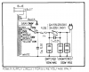
The 2.2m(R-1) resistor is used to bleed off RF (antenna strikes, near strikes, etc. to chassis) from the cord. At least that's my understanding. Most have an 820kΩ resistor, but the 1010 & the 939 show 2.2m. The following extract is from the SX-1010 "F", GN", & "KCU" Subtype schematic. Note the resistor. It looks like it was originally installed. As you're running single phase 120v 60Hz, I'd put it in. And orient the plug as noted by Merlynski.
ScreenHunter 284.jpg

The 1010 I had was also a "F" sub-model and DID HAVE the 2.2MΩ resistor as outlined above by the OP.
 
Yeah, thanks guys, I will put the resistor there.

But now I wonder if I have the correct schematics, because this is what is shown on the one I have...
upload_2020-12-21_16-12-17.png

Which is a high res scan I found on a thread on this forum...
 
It's essentially the same circuit electrically, the only difference is the multiple transformer taps. Set it for 130V (higher than your line voltage) so it won't run 1.) at the ragged edge of voltage & 2.) with more turns being used, it will tend to be a bit cooler.
 
Back
Top Bottom