• The move to the new server is done. There are some software and database maintenance updates in process. This has us passing the hat around to help out. We appreciate any donations. Seriously, even a dollar helps. The payment page may be found here - https://www.audiokarma.org/support.html

Pioneer SX-1050 has a dead channel

Rob357

New Member
Oops, I had to correct the header! Hello to all the enthusiasts out there. I have been lurking around here since 7/1/2007. My only post was to list my Pioneer gear. Now I am asking for some advice. The 1050 had a low and distorted right channel, that is what started this odyssey. I had recapped the awr-103a board awhile ago, not much else had been done. When I turned the amp up, it went into protection. I realized after replacing the transistors and diodes on the protection board, that I had never done the caps. I went with a full recap using the parts lists found on this forum, including using the stacked film for the dreaded .22uf Sanyo light blue ones. I also put in a new relay. Still had the low channel but it no longer went into protection. In the investigation of the problem I have managed to kill the right channel completely, Grrrr. I pulled the pre out to amp jumpers and both pre amps sound good. So the problem is in the right channel amp. All the voltages from the power supply and protection board are within specs. Now I am not sure where to start. Any help would be greatly appreciated. I am more a part replacer than a technician. That needs to change. Thoughts?
 
Register to hide this ad
Simple things to try. check DC off set. Idle current see if there is any issues. I would replace the tantalum caps if they are still in there. They are known to fail.
 
I forgot to mention the DC offset and idle current are OK. Could I have damaged something while setting them?
Do you know the values of the tantalum caps by chance? Can I use the stacked film version there?
Thanks for the tip!
 
they are .68uf 25v. Most guys are using wima films for the replacement. they make a .68uf 50v or 63v that will work.
 
That board is a pita to get out. Might as well do everything that is recommended. I would like to fix the channel before I start making wholesale changes. That way lies madness.
 
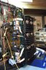
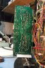
Mouser # 667-ECW-FD2W684J4 is what I put in mine for the 0.68µF on the power amp. Do you already have the board removed? You can stand the receiver on one end, remove the heatsink with output transistors, loosen a bunch of the harness clips and wires (without disconnecting), swing out the power amp pcb, support the pcb with a small vise, support the heatsink with another small vise, reconnect output plugs to pcb and work on the whole thing, electrically fully connected and fully accessible, both sides of the pcb, and the heatsink, and all the pins. Mine is setting on a 15" lazy susan type turntable to make it easy to rotate.

DSCF1073 (2).JPG


DSCF1071.JPG

DSCF1044.JPG
 
That setup is genius. I have two panavise to hold them as well. Now onto where did my sound go? The voltage at the output transistors looks good.
 
Yes switches are clean, the pre out test clears the preamp. It was low and distorted before it went silent. I mean silent, nothing on that side. Nothing on the headphones either. Last thing I did was set the offset and bias.
 
When you checked the dc off set was it at the speaker terminals or the Pins of the board? the relay you replaced on the protection board is in between the amp and the speaker terminals. Are the connections on the relay good?
 
Measured at the pins as per the manual. If I turned one of the pots voltage up too high, could I have damaged something? I will double check the solders on the relay, they looked good but it's worth firing up the iron to be sure.
 
You can damage output transistors,, driver transistors, and maybe other things by turning the bias up too much, but if no magic smoke escaped you may not have gone too far and if it was only that way for a short time.
 
I pulled the protection board. All the solders look nice and shiny. But that pesky broken orange wire on terminal 9 might be an issue. I re-soldered the wire and now have both channels that sound good! Volume and sound quality are back. Now it's time to recap and replace problem parts for longevity. Thanks to Lowetlx for asking me to revisit the protection board. Too much twisting to unsolder and replace parts. Thank to merlynski for the advice and photos of how to set up the board for repair. Is there a latest parts list for the sx-1050The word docs are a non starter for those that don't have word. I should convert them to PDF for ease of viewing.
 
Here is the one I have worked from (on mine), cannot guarantee it is complete, but it has transistors, caps, a few resistors, and the relays. Caveats: the big power supply filter caps are a 50% increase in capacitance (drop in fit, screw posts), the list contains film caps for signal path caps from 10µF and below. Fitting some of them requires a bit of creativity, I moved a resistor to the bottom of the board in one case, and installed the cap on the bottom in another case, did a bit of custom lead bending to get some to fit, but they all did. Most of the small transistors (TO-92, TO-126) I ordered 100 of each, instead of just what is in the list.
Mouser part numbers.
 

Attachments

Great that you have it working. Merlynski has a nice set up there. I went about the power amp slightly differently. Either way will work. I disconnected the output harnesses and numbered them. I unbolted the STV's from the heat sink. Unbolted the board from the heat sink. then unbolted the heat sink from the chassis and lifted the heat sink out from the top. Once removed I carefully unsoldered the stv's from the board and set them someplace safe. I then set the unit on its side. I unfastened the harness below and pulled the board through the hole In the chassis and was able to work on it that way. I also numbered the outputs. removed them, cleaned the heatsink, outputs, the connectors and the pins. Then reset with new compound and mica insulators.
 
Lowetlx, I did exactly what you described, except I unmounted and then reinforced the STV wires at the body of the STV and did not unsolder them. When I connected the heatsink and outputs to the PCB I remounted the STVs on the heatsink with a dab of heatsink compound. The circuit was connected electrically exactly as it would be when fully installed in the chassis. I was able to set bias and dc offset, then play music to get the heatsink, output transistors and the STVs up to operating temperature to verify full functionality. After I verified function I turned the bias back to minimum, unmounted the STVs, reinstalled the pcb and heatsink, remounted the STVs and then set the bias to its final value, after warmup again. I did replace the output transistors with new ones.

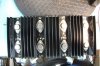
Heatsink and power transistor labeled so as not to mix them up:

DSCF1052.JPG


I also smoothed and flattened the raised transistor mounting surface with a fine file for better thermal conductivity:

DSCF1061.JPG

I was surprised how un-flat they were, especially where the transistor die is mounted inside the transistor.
 
I got the driver transistors and mica for those and the outputs. New power cans and a lot of other transistors and caps. I would like to make it as bullet proof as possible, as it is my bench amp/receiver. I did get the turntable in 15". That is cheating putting the NPN and PNP along with the numbers. That looks like something my dear departed psychedelic relic ex navy god of a tech would have done. Fred Thompson was "The Man" I hope to one day stand proud in his shadow. I am lucky to have inherited his wooden bench and patch panel. I will post a photo of that later.
 
Mouser # 667-ECW-FD2W684J4 is what I put in mine for the 0.68µF on the power amp. Do you already have the board removed? You can stand the receiver on one end, remove the heatsink with output transistors, loosen a bunch of the harness clips and wires (without disconnecting), swing out the power amp pcb, support the pcb with a small vise, support the heatsink with another small vise, reconnect output plugs to pcb and work on the whole thing, electrically fully connected and fully accessible, both sides of the pcb, and the heatsink, and all the pins. Mine is setting on a 15" lazy susan type turntable to make it easy to rotate.

View attachment 2029434


View attachment 2029440

View attachment 2029439

Dear Rob357 how can i get this Rotary Table ?
 
Back
Top Bottom