• The move to the new server is done. There are some software and database maintenance updates in process. This has us passing the hat around to help out. We appreciate any donations. Seriously, even a dollar helps. The payment page may be found here - https://www.audiokarma.org/support.html

Pioneer SX-1050 Output Transistor Help

Bradley J

New Member
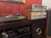
Hi everyone, about 6 months ago I had 4 speakers hooked up to my 1050 and I made the great mistake of dropping the needle too hard on one of my Zeppelin records. The pop was quite loud and it killed my 1050 as well. It only popped the main 10A fuse on the rear and nothing else. No smoking or any foul smell.

After months of researching the forums here and gathering parts that I believe I need, I now feel stumped when it comes to tracing back the damage that has been done. It seems that I shorted my output transistors but I don't think those just go out due to something like this. There has to be something else deeper that caused this. (At least that is what I think). I have new output transistors on order and they're being shipped currently. I also found 4 NOS STV-3H in case those are needed as well. Also going to be checking the resistors on the power assembly board. Other than that, I have no idea what to troubleshoot or test using my DMM or even how to test some things.

Any help or guidance would be very appreciated since it is only me, myself, and I in my area who can work on this thing. I do have previous experience recapping a few miscellaneous receivers, tape decks, and repairing leads on a Nakamichi PCB. Other than straightforward repairs like that, I do not have experience troubleshooting faulty equipment or tracing problems like this. And yes I'm making a dim bulb tester over the next day or two... I am just taking it slow and taking in more research and knowledge so I don't do shotgun-type repairs which will lead to more trouble down the road. I really care about my equipment and I hope to enjoy my monster 1050 for the rest of my life.

Thanks for the help. And go easy on me... I'm only 19 and still learning the ropes...:bowdown:
 

Attachments

  • SX-1050 on the desk.png
    SX-1050 on the desk.png
    717.5 KB · Views: 26
Register to hide this ad
Those absolutely go out due to something like this.

Check all the emitter resistors and resistors under heat tubing, and of course all transistors on the amp board. I highly doubt the bias diodes died. Why did you order some when you can just test them first?

The nice thing about Pioneers is that when they blow, they make it very obvious what headed for the door.
 
get an active transistor tester. It will serve you well.
even if you only get a chineseium transistor tester on eprey for $20,
better would be a peak atlas DCA 55 tester,
 
Last edited:
Those absolutely go out due to something like this.

Check all the emitter resistors and resistors under heat tubing, and of course all transistors on the amp board. I highly doubt the bias diodes died. Why did you order some when you can just test them first?

The nice thing about Pioneers is that when they blow, they make it very obvious what headed for the door.
Thanks for the reply and I will be checking those transistors on the amp board. Also, what do you mean by heat tubing? I'm not quite sure where that would be.

I ordered them for the "in case" factor I guess. I wasn't sure at the time or even now how to test them and what to even read if I were to test them. And I'll probably go ahead and order one of those Peak Atlas testers like Mark recommended.
 
Thanks for the reply and I will be checking those transistors on the amp board. Also, what do you mean by heat tubing? I'm not quite sure where that would be.

I ordered them for the "in case" factor I guess. I wasn't sure at the time or even now how to test them and what to even read if I were to test them. And I'll probably go ahead and order one of those Peak Atlas testers like Mark recommended.
It's like white/tan braided tubing over several resistors on the amp board, sorry, can't really describe it better than that.
 
Those absolutely go out due to something like this.

Check all the emitter resistors and resistors under heat tubing, and of course all transistors on the amp board. I highly doubt the bias diodes died. Why did you order some when you can just test them first?

The nice thing about Pioneers is that when they blow, they make it very obvious what headed for the door.

Alright here's a bit of an update...
So I upgraded my o/p transistors with the recommended PNP & NPN OnSemi ones and then tested all STV-3H (checked out). Went ahead and used my DBT when powering on the unit and it failed. The bulb went bright and the unit didn't even power up. Assuming it went into protection mode.

Then I went ahead and unplugged the o/p transistors from the amp board entirely in which the unit passed the DBT and powered up perfectly. I thought that was quite odd so I did some more testing by plugging in only one channel of o/p transistors at a time and found only the left side is causing the short and the right side passes the DBT. Moved o/p transistors around on the heat sink from one side to the other and ruled out those being at fault as the short still persisted on the left side of the board.

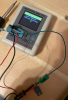
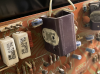
Tested Q18, Q20, Q14, and Q16. Found that Q18 and Q14 aren't good and they must be causing the short. Just ordered a rebuild kit for the amp board and I'll go from there and see what that'll do replacing all the faulty transistors.
 

Attachments

  • Screen Shot 2022-06-06 at 10.55.51 PM.png
    Screen Shot 2022-06-06 at 10.55.51 PM.png
    820.7 KB · Views: 27
  • Screen Shot 2022-06-06 at 10.55.59 PM.png
    Screen Shot 2022-06-06 at 10.55.59 PM.png
    1,015.9 KB · Views: 30
  • Screen Shot 2022-06-06 at 10.56.08 PM.png
    Screen Shot 2022-06-06 at 10.56.08 PM.png
    762 KB · Views: 30
What does the kit include? MJE15032/3 are always the recommended drivers but the bias sometimes can't get dialed in with them. KSC2073/KSA940 may be a better choice.
Hope the kit also has the trimmers and input pair transistors.
 

Attachments

  • 6C85B878-FCC2-407C-AF0F-E33EFB0A9EB3.jpeg
    6C85B878-FCC2-407C-AF0F-E33EFB0A9EB3.jpeg
    139.4 KB · Views: 14
What does the kit include? MJE15032/3 are always the recommended drivers but the bias sometimes can't get dialed in with them. KSC2073/KSA940 may be a better choice.
Hope the kit also has the trimmers and input pair transistors.

The recommended drivers I usually see on audiokarma are KSA940/KSC2073. Not sure I’ve seen the MJE pairs recommended here.
 
Pulled Q18 & Q17. Both 2SB536. My suspicion was right about Q18 as it doesn’t pass the continuity test. Is it common for these to pop when o/p transistors go out too?
 
q17 is left channel, q18 is right channel.

both got the impossible demand, driver and output.

some circuit fragments shrug off overloads, but the power amp inherently can't.

plus the SX-1050 power amp topology is somewhat different from that found in many other models.
 
q17 is left channel, q18 is right channel.

both got the impossible demand, driver and output.

some circuit fragments shrug off overloads, but the power amp inherently can't.

plus the SX-1050 power amp topology is somewhat different from that found in many other models.
Ahh ok I must have the board mixed in my head. *I guess it’s the right channel with all the issues so change what all I said to it being a right channel issue* I just assumed when looking at the board, the left side is the left channel.

With that being said, is there any chance something popped on AWR-103? Or will everything be contained to just the amp board? Thanks!
 
read the voltages, regulated must be within +/- 5%
1, 2, 3 are raw dc off the power line +/- 10% or even a bit more.

insulate (tape) your (red) probe, all but a tiny portion of tip for when you slip (we ALL slip!!)
black probe to bare metal chassis ground.

read this
plus the search feature is your friend. have it search for awr-103. there is a picture heavy recent thread in that bunch.

https://audiokarma.org/forums/index...tput-caps-problem.979919/page-6#post-15262133
Pin1= 22.3v
Pin2=72.5v
Pin3= -74v
Pin4= 0 ground
Pin5=13.4v
Pin6=13.4v
Pin7= -13.4v
Pin8= -62.7v
Pin9= -32.0v
Pin10= -26.0v
Pin11= -26.0v
Pin12=0 ground
Pin13=25.2v
Pin14=25.2v
Pin15=31.2v
Pin16=61.4v
Pin17=61.4v
Pin18=5.34v
Pin19=5.34v

upload_2022-6-7_23-30-55.png
 
Welp… I feel like I’m getting to the point of giving up currently.

Just finished going over the whole amp board with that rebuild kit. Taking my time and doing a tidy job. Came time to turn the unit back on and the DBT dimmed down but the unit’s relays didn't kick on. Then smoke started coming from somewhere around R32 on the right channel of the amp board. Don’t know exactly what was smoking but I believe it might’ve been the R32 resistor. Can’t seem to find any burnt components.

I then unplugged the right channel outputs but kept the left channel connected to the amp board. Fired it back up and the DBT dimmed down BUT the relays kicked on out of protection. Then again though, smoke from the same area of the board.

Feel very lost at this point and seems like a real rabbit hole. Now it’s time for some Aspirin and meditation…:eek::confused:
 
Finally sat down and took some time with the schematics tracing the issue. Feeling quite dumb now but what I thought was R31 was actually R32 smoking. And I found out that I read the schematic wrong when installing Q7 and was reading the pin out for Q8 on the flip side of the board. Removed Q8 and it tested ok then finally reinstalled it in the correct orientation.

That fixed everything and I have a working 1050 again after 6 months. Adjusted all the new trimmers to spec and it’s being tested now and it sounds phenomenal. Boy I missed this unit. Going to be doing an overhaul with a complete rebuild kit here soon. Just glad I was able to get it back up and running.

Thank you Ivan and Mark for the help over the last couple weeks. Both of your knowledge/information are valued greatly with me! Can’t wait to hear my 1050 paired with my Marantz HD-880s I’m about to purchase from a friend!
 

Attachments

  • BDFC3262-1E17-494C-9509-4484677E426F.jpeg
    BDFC3262-1E17-494C-9509-4484677E426F.jpeg
    108.3 KB · Views: 13
Back
Top Bottom