• The move to the new server is done. There are some software and database maintenance updates in process. This has us passing the hat around to help out. We appreciate any donations. Seriously, even a dollar helps. The payment page may be found here - https://www.audiokarma.org/support.html

Pioneer SX-1250 intermittent protection relay clicking

qguy

Super Member
I was advised to provide measurements when the relay was not clicking, but when I turned it on today, the relay clicked, but it was intermittent, should I just do a blanket parts replacement on the protection board?

sx-1250,awm-091,C1,470,6,cea,,470,10,647-UPW1C471MPD6
sx-1250,awm-091,C2,470,6,cea,,470,10,647-UPW1C471MPD6
sx-1250,awm-091,C3,4.7,25,cea,,4.7,50,647-UPW1H4R7MDD
sx-1250,awm-091,C4,100,16,cea,,100,16,647-UPW1C101MED
sx-1250,awm-091,C5,100,50,cea,,100,50,647-UPW1H101MPD
sx-1250,awm-091,C6,100,50,cea,,100,50,647-UPW1H101MPD
sx-1250,awm-091,q1,2sc945,,diff,,,,512-KSC1845FTA
sx-1250,awm-091,q2,2sc945,,diff,,,,512-KSC1845FTA
sx-1250,awm-091,q3,2sa733,,or logic,,,,512-KSA992FBU
sx-1250,awm-091,q4,2sc945,,current dump,,,,512-KSC2383YTA
sx-1250,awm-091,q5,2sc1166,,relay drive,,,,512-KSC2690AYS
sx-1250,awm-091,q6,2sc1166,,v reg,,,,512-KSC2690AYS
 
Register to hide this ad
I was advised to provide measurements when the relay was not clicking, but when I turned it on today, the relay clicked, but it was intermittent, should I just do a blanket parts replacement on the protection board?

sx-1250,awm-091,C1,470,6,cea,,470,10,647-UPW1C471MPD6
sx-1250,awm-091,C2,470,6,cea,,470,10,647-UPW1C471MPD6
sx-1250,awm-091,C3,4.7,25,cea,,4.7,50,647-UPW1H4R7MDD
sx-1250,awm-091,C4,100,16,cea,,100,16,647-UPW1C101MED
sx-1250,awm-091,C5,100,50,cea,,100,50,647-UPW1H101MPD
sx-1250,awm-091,C6,100,50,cea,,100,50,647-UPW1H101MPD
sx-1250,awm-091,q1,2sc945,,diff,,,,512-KSC1845FTA
sx-1250,awm-091,q2,2sc945,,diff,,,,512-KSC1845FTA
sx-1250,awm-091,q3,2sa733,,or logic,,,,512-KSA992FBU
sx-1250,awm-091,q4,2sc945,,current dump,,,,512-KSC2383YTA
sx-1250,awm-091,q5,2sc1166,,relay drive,,,,512-KSC2690AYS
sx-1250,awm-091,q6,2sc1166,,v reg,,,,512-KSC2690AYS
Perhaps, are you sure the protection board is the issue? It may be a power amp with unstable DC offset.

Have you looked at the amplifier offset voltages at either the output of the amplifiers or the inputs of the protection board?
You can't see the offset voltages at the speaker terminals if the relay is not closed.
 
Take voltage readings at all the pins on the protection board noting that one may be in AC volts. Regardless of the relay working or not.
 
Take voltage readings at all the pins on the protection board noting that one may be in AC volts. Regardless of the relay working or not.
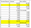
Here you go...

Yellow is AC

was not able to get reading while the relay was clicked on pin 12, the relay would not engage even after an hour
Pin 5 Not clicked, does not stop at a certain voltage but shifts from 7-11volts
Pin 12 Not clicked, starts from 24 down to 0 in 1 second

1755671749852.png
 
Last edited:
Here you go...

Yellow is AC

was not able to get reading while the relay was clicked on pin 12, the relay would not engage even after an hour
Pin 5 Not clicked, does not stop at a certain voltage but shifts from 7-11volts
Pin 12 Not clicked, starts from 24 down to 0 in 1 second

View attachment 3577972
Couple of things. You should annotate your chart readings. + VDC or -VDC. Or a shorter form +24V +24mV -24V -24mV etc.
You did note yellow for AC :thumbsup: you can just call it out as VAC or mVAC.
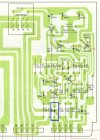
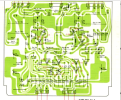
Pins 6 and 9 are the amplifier audio outputs. In normal operation we would expect a very low value, say + or - 10 to 80 mVDC. Zero is good, but typically I would expect some low value of + or - millavolts, and they almost always wobble around a little bit. Are you using an auto ranging meter?

Unless there is an issue on one of the amp boards the voltage on pin 5 should be stable. Pin 5 is the sum of the amplifier overload circuits.
You can lift one end of D3 to "turn off" that part of the circuit and see if the protection circuit operates.

1250prot1.jpg

I know you were asked for all terminals. The 1250 protection board also has the main amp PS rectifiers on it and is mostly of no concern for your problem.
Pins 10 through 14 are the PS pins.

That said some of the PS pin readings are odd. Here is what is going on.

Pins 10 & 11 are the AC input voltage. The AC voltage from 10 to ground and 11 to ground should be the same.
Pin 12 + voltage for amplifier output stage. +70 in normal operation.
Pin 13 - voltage for amplifier output stage. -70 in normal operation.
Pin 14 + and - 70 volt supply ground.

I'm guessing that the pin 12 reading was just a bad connection. And speaking of bad connections the pins and plugs on the boards do oxidize and can cause trouble.
 
These protection board voltages are optimum:
pin 1 +65v DC,
pin 2 7.5v AC
pin 3 -24v DC
pin 5 closer to +20v DC (is good). Or +3v DC if overcurrent triggering (Bad)
pin 6 0.000v DC (note in mV's)
pin 9 0.000v DC (note in mV's)

Q11 on the amp boards can be causing trouble.
Check the amp settings (Idles and DC Balance) for correct voltages and stability before condemning Q11 and C11.

This will be an incremental fix, because it is possible that the protection is operating correctly and something is going wrong to cause it to want to go into protection.
IF you are willing, we can trade troubleshooting for (delayed - but eventually....) parts replacement.
But due to my online timings, the troubleshooting will be a slow cycle.

The cycle timings - the time part spent IN protect - are important - we are looking to see if the protect circuit is violating the "power up time delay". If it isn't, then it isn't the relay drive transistor, and something else is causing a genuine protect.

first thing - freeze spraying the power supply - nah, freeze spray the Q5 2sc1166 relay drive transistor on the protect board, up top of the board, the transistor closest to the relay... (nice that it's easy to access)

restoration order:
protection board
(power supply rebuild optional at this point - but I would do it even if it didn't address an immediate failure)
power amp boards protect function parts C11 and Q11
power amp board in general.

each of these lines also represents a stopping point to re examine the progress in curing the fault.

Quite frankly, the rebuilds are so quick I generally just do the four boards at one fell swoop and be done with it. I spend more time cleaning them afterward (and during - on the component side).
 
Last edited:
Q11 on the amp boards can be causing trouble.
Check the amp settings (Idles and DC Balance) for correct voltages and stability before condemning Q11 and C11.
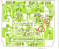
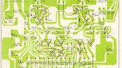
Not sure if my eyes are failing me, but I can't identify which is Q11 and C11, does anyone have a source for a better service manual, I got this from the AK site...

1756043188618.png
 
Can I install left channel board and test if the relay clicks without installing the right channel board? if Ok, then add the second board?

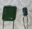
For C11 0.22 uf 10v. On the power amp board, which one do I use? these are the only ones I can find locally

1756278139213.png
 
Last edited:
Replace Q11 and C11, tested with DBT, bright light, then dims, then relay clicks, YEY !!! Remove DBT relay does not click, huh??? Anyways will just send this to a pro as I don't want to mess with the receiver anymore for fear of damaging it....
 
Back
Top Bottom